Supercharge Your Innovation With Domain-Expert AI Agents!

Finite element numerical model debugging method based on grid structure

A grid structure and numerical model technology, applied in electrical digital data processing, special data processing applications, instruments, etc., can solve problems such as time-consuming, inability to calculate, and distortion of calculation results, and achieve the effect of overcoming time-consuming and labor-intensive

Inactive Publication Date: 2012-08-15
HOHAI UNIV
View PDF4 Cites 0 Cited by
  • Summary
  • Abstract
  • Description
  • Claims
  • Application Information

AI Technical Summary

Problems solved by technology

In the construction of models under complex conditions such as dam abutments, large underground caverns, and complex components, due to the complex geometric conditions of the structures and the influence of the intersecting relationship of the structural plane space, a little carelessness may cause errors in the model, making the calculation The result is distorted and cannot even be calculated
In order to find out the source of the error, the common method is to check from the point-line-surface modeling process, and to traverse in a certain order, such as point-by-point, line-by-line, and surface-by-surface inspection along the coordinate axis of the model ; If there are many errors in the model, it needs to be eliminated one by one, and repeated many times. It is relatively easy for a simple finite element model. If the number of nodes and elements of the finite element model is tens of thousands or even hundreds of thousands or millions, use ordinary models to check for errors The method seems powerless, not only consumes a lot of time, but also reworks many times, causing researchers to lose patience

Method used


Image

  • Finite element numerical model debugging method based on grid structure
  • Finite element numerical model debugging method based on grid structure
  • Finite element numerical model debugging method based on grid structure

Examples


Embodiment 1

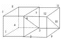
[0046] Step 1 A simple model is a cuboid, such as Figure 4 As shown, point 1 coordinates (0, 0, 0), point 2 coordinates (10, 0, 0), point 3 coordinates (10, 10, 0), point 4 coordinates (0, 10, 0), point 5 coordinates (0, 0, 10), point 6 coordinates (10, 0, 10), point 7 coordinates (10, 10, 10), point 8 coordinates (0, 10, 10), point 9 coordinates (20, 0, 0 ), the coordinates of point 10 (20, 10, 0), the coordinates of point 11 (10, 10, 10), the coordinates of point 12 (20, 0, 10), and the finite segmentation is divided into two hexahedral 8-node units ( Figure 4 ), then according to the aforementioned node numbering rules, the number of unit 1 can be written as: 1 2 3 4 5 6 7 8, and the number of unit 2 can be written as 2 9 10 3 6 12 11 7. The number of units is 2, and the number of nodes is 12.

[0047] Step 2 Number the surface elements in the 2 hexahedral 8-node units, the 6 surface elements of unit 1 are 1 2 3 4; 2 6 7 3; 3 7 8 4; 4 8 5 1; 1 5 6 2; 5 8 7 6; the 6 bin...

Embodiment 2

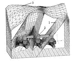
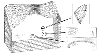
[0053] Example 2: Troubleshooting and analysis of the 3D finite element model of the complex structure of a surge well engineering area of ​​a hydropower station. The model includes micro-new rock mass, weakly weathered lower rock mass, weakly weathered upper rock mass, strongly weathered rock mass, and fault F 20 , F 21 , F 22 and other rock formations, the underground structures include 3 surge shafts, 3 tailrace tunnels, 9 tailrace tunnels, connecting upper chambers, etc. The schematic diagram is as follows Figure 6 shown. After the initial modeling is completed, the numerical software trial calculation fails, and the system prompts that the local deformation is too large. Application of the present invention to check the error step is as follows:

[0054] (1) Classify the finite element grid information into node information and unit structure information, including the number of nodes and units, node coordinates, unit structure shape, information on building unit stru...


PUM


Abstract

The invention relates to a finite element numerical model debugging method based on a grid structure, which comprises the following steps of: dividing a geologic model into a plurality of tetrahedron four-node, pentahedron six-node and hexahedron eight-node grid objects; converting the tetrahedron four-node and pentahedron six-node grid objects into hexahedron eight-node grid objects; classifyingunit information by using the hexahedron eight-node grid objects and the hexahedron eight-node grid objects which are obtained by converting the tetrahedron four-node and pentahedron six-node grid objects as units to obtain node and structure information;; numbering the nodes according to the node position and the anticlockwise sequence from bottom to top; numbering plane elements in all the hexahedron eight-node units, i.e. making all nodes point to the inner part of the unit according to the right hand rule; combining the node number in the plane elements to obtain the plane element code; and carrying out area retrieval in 6*ne plane elements and removing zero-area plane elements, left, right, front, back, upper and lower boundaries and public plane elements, wherein the residual plane element is the probable model error position.

Description

technical field [0001] The invention relates to the preprocessing part in the field of engineering numerical analysis such as civil engineering. Background technique [0002] Numerical simulation technology is an important means of mechanical analysis in civil engineering, and geological modeling is the main component of the pre-processing of numerical simulation technology. In the construction of models under complex conditions such as dam abutments, large underground caverns, and complex components, due to the complex geometric conditions of the structures and the influence of the intersecting relationship of the structural plane space, a little carelessness may cause errors in the model, making the calculation The result is distorted and cannot even be calculated. In order to find out the source of the error, the common method is to check from the point-line-surface modeling process, and to traverse in a certain order, such as point-by-point, line-by-line, and surface-by...

Claims


Application Information

Patent Timeline
Patent Type & Authority Patents(China)
IPC IPC(8): G06F17/50
Inventor 石崇徐卫亚聂卫平
Owner HOHAI UNIV
Features
  • R&D
  • Intellectual Property
  • Life Sciences
  • Materials
  • Tech Scout
  • Unparalleled Data Quality
  • Higher Quality Content
  • 60% Fewer Hallucinations
Learn More