
Displayport signal transmission line for computer

A signal transmission line and signal line technology, which is applied in the direction of communication cables, electrical components, cables with twisted pairs/quadruple pairs, etc., can solve the problem of cumbersome signal transmission line processing procedures, poor anti-EMI ability, slow transmission speed, etc. Stability and other issues, to achieve the effect of fast signal transmission, strong EMI resistance, and increased shielding effect

Inactive Publication Date: 2011-05-18
WEIHAI HONGLIN WIRE & CABLE
View PDF0 Cites 3 Cited by
  • Summary
  • Abstract
  • Description
  • Claims
  • Application Information

AI Technical Summary

Problems solved by technology

[0002] With the development of science and technology, there are more and more occasions for the application of digital signal transmission, especially high-end display equipment such as scientific research and medical equipment. The existing digital signal transmission line is composed of five pairs of signal lines and five electronic lines. Then Wrapped by aluminum foil, in which the signal line is formed by twisted core wires, blue single-sided aluminum foil shielding is used outside the twisted signal line, and the whole wire harness is braided with aluminum foil and conductive metal wire as the outer shield, and then PVC protection is added outside the outer shield Sleeve layer, this kind of structural signal has the disadvantages of unstable transmission speed, poor anti-EMI ability, low transmission speed bandwidth, signal transmission line has cumbersome processing procedures, long production cycle, high cost, etc.

Method used


Image

  • Displayport signal transmission line for computer
  • Displayport signal transmission line for computer

Examples


Embodiment Construction

[0009] The present invention will be further described below in conjunction with accompanying drawing:

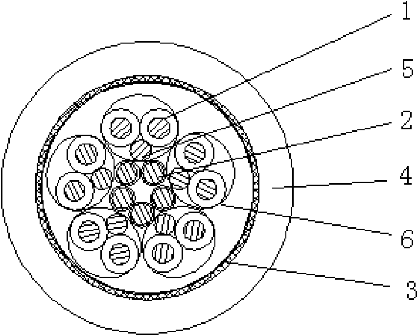
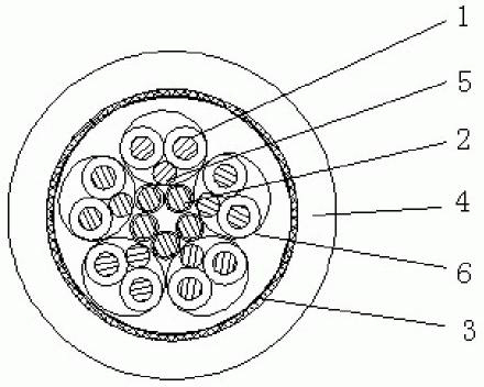
[0010] As shown in the accompanying drawings, a Displayport signal transmission line for computers includes five pairs of signal lines 1, five electronic lines 2, an outer shielding layer 3 and a sheath layer 4, and is characterized in that each pair of signal lines 1 is equipped with a grounding The wire 5 is wrapped with double-sided mylar to form an inner shielding layer 6. After five signal wires 1 and grounding wires 5 wrapped with an inner shielding layer 6 form a wiring harness with five electronic wires 2, aluminum foil and conductive metal wire are used as a braided wire harness. The outer shielding layer 3 is provided with a PVC sheath layer 4, and the five electronic wires 2 of the present invention are surrounded by five signal wires 1 and grounding wires 5 wrapped with an inner shielding layer 3 in the center, increasing shielding effect, prolonging the service...


PUM


Abstract

The invention relates to transmission of digital signals, in particular to a Displayport digital access signal transmission line suitable for computers, liquid crystal display televisions, digital light processing (DLP) large screen displays, high-end 3DLP projectors and other pieces of high-end display equipment. The Displayport digital access signal transmission line comprises five pairs of signal wires, and five electronic wires, an outer shielding layer and a jacket layer, and is characterized in that: each pair of signal wires and an earth wire are matched and are wrapped by a double-sided Mylar so as to form an inner shielding layer, five signal wires wrapped with the inner shielding layers, an earth wire and the five electronic wires form a wire harness, and the outer shielding layer is woven from an aluminum foil and a conductive metal wire; and the polyvinyl chloride (PVC) jacket layer is arranged on the outer shielding layer. Due to the adoption of the structure, the double-sided Mylar wrapping insulativity of the transmission line can reach 100 megohms, and the near-end and far-end cross talk exceeds the standard requirements of a video electronics standards association (VESA) and the transmission line has the advantages of simple process, low cost, higher efficiency, high tensile strength, long service life, small interference with signal transmission, stability in signal transmission and the like.

Description

Technical field: [0001] The invention relates to a digital signal transmission line, in particular to a Displayport digital access signal transmission line suitable for display devices such as computers, liquid crystal televisions, DLP large-screen displays, and high-end 3-DLP projectors. Background technique: [0002] With the development of science and technology, there are more and more occasions for the application of digital signal transmission, especially high-end display equipment such as scientific research and medical equipment. The existing digital signal transmission line is composed of five pairs of signal lines and five electronic lines. Then Wrapped by aluminum foil, in which the signal line is formed by twisted core wires, blue single-sided aluminum foil shielding is used outside the twisted signal line, and the whole wire harness is braided with aluminum foil and conductive metal wire as the outer shield, and then PVC protection is added outside the outer shie...

Claims


Application Information

Patent Timeline
Patent Type & Authority Applications(China)
IPC IPC(8): H01B11/00H01B11/06
Inventor 田洪杰
Owner WEIHAI HONGLIN WIRE & CABLE
Learn More