Pressure-proof proportion electromagnet based on integrated type flux sleeve

A technology of proportional electromagnet and magnetic sleeve, applied in the direction of electromagnet with armature, electromagnet, valve operation/release device, etc., can solve the problems of thin wall of magnetic sleeve and limited pressure of magnetic sleeve, and achieve reduction Effects of complexity, simplification of processing technology, and cost reduction

Inactive Publication Date: 2011-05-18
ZHEJIANG UNIV
View PDF4 Cites 16 Cited by
  • Summary
  • Abstract
  • Description
  • Claims
  • Application Information

AI Technical Summary

Problems solved by technology

However, this electromagnet also has the disadvantage that the sleeve wall at the groove of the magnetic sleeve is thin and long, resulting in limited pressure inside the magnetic sleeve.

Method used


Image

  • Pressure-proof proportion electromagnet based on integrated type flux sleeve
  • Pressure-proof proportion electromagnet based on integrated type flux sleeve
  • Pressure-proof proportion electromagnet based on integrated type flux sleeve

Examples


Embodiment 1

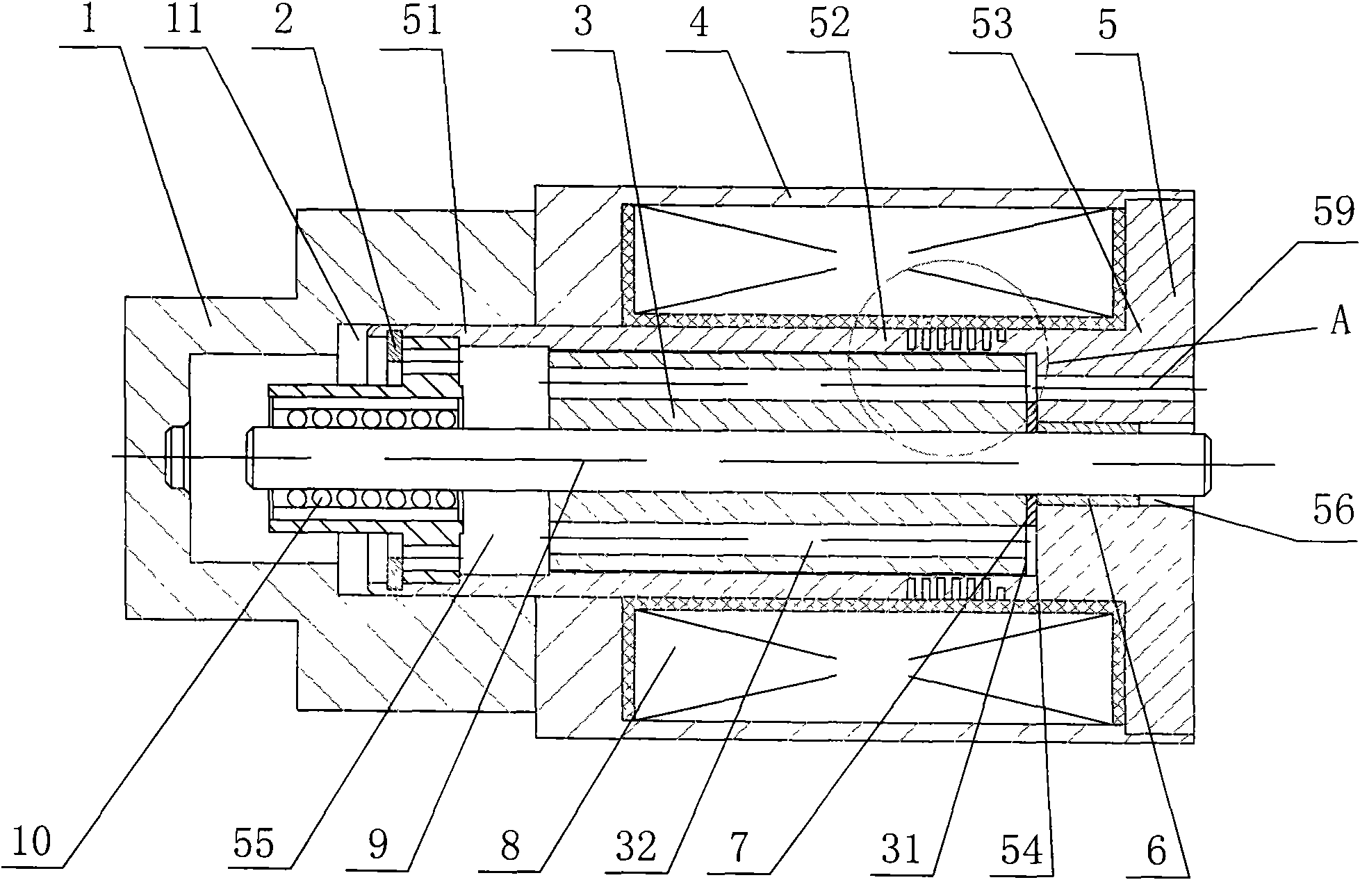
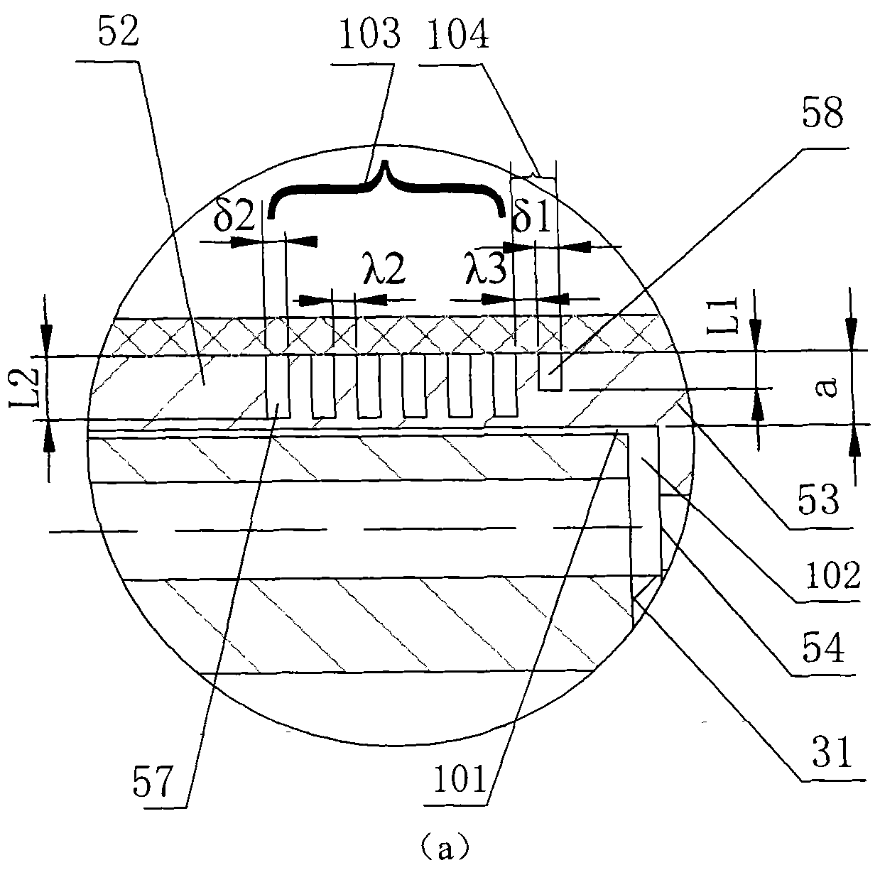
[0047] Embodiment 1, figure 1 with figure 2 (a) Combined with a pressure-resistant proportional electromagnet based on an integrated magnetic sleeve, it includes a housing 4 with a rectangular parallelepiped shape and a cylindrical inner hole, and a magnetic sleeve 5 with a stepped cylindrical shape And the end cover 1 with the end cover cavity 11 inside; the magnetic sleeve 5 is set in the housing 4 , and the control coil 8 is arranged between the magnetic sleeve 5 and the housing 4 . The control coil 8 can be selected as a concentric solenoid control coil. An opening is provided on the casing 4 for installing a socket and connecting with the control electronic circuit; that is, the control coil 8 can use this opening to realize electrical connection with the outside world.

[0048] The magnetic sleeve 5 is composed of a front section 51 , a middle section 52 and a rear section 53 which are sequentially connected from left to right. Rear section 53 is combined by small c...

Embodiment 2

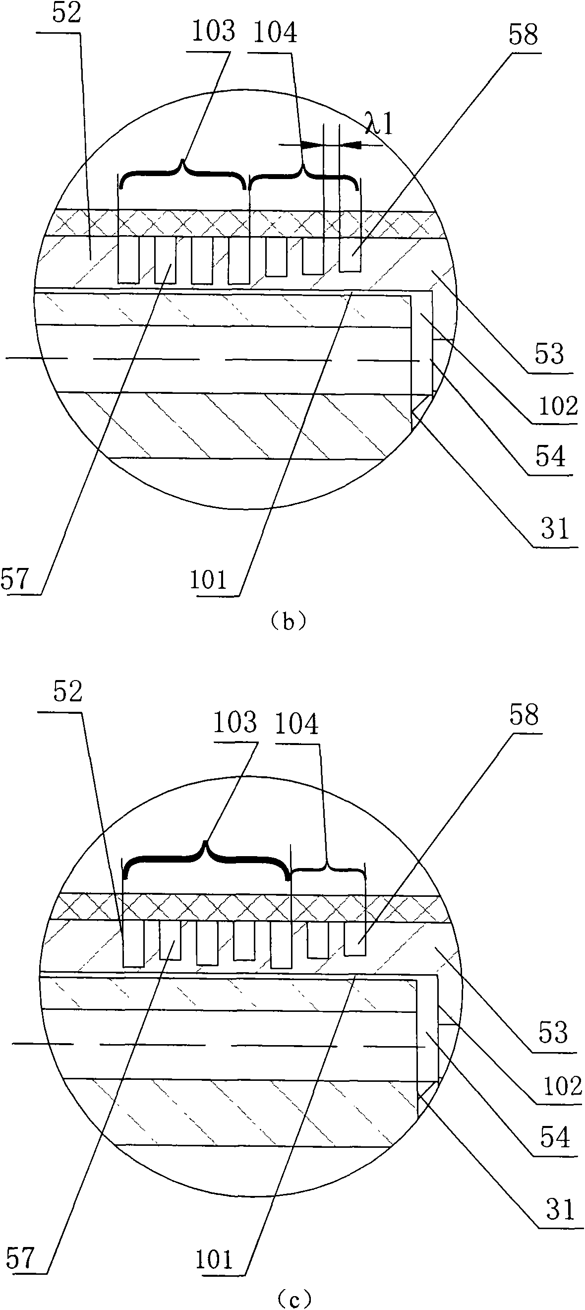
[0069] Embodiment 2, figure 1 with figure 2 (b) Combined with another pressure-resistant proportional electromagnet based on an integrated magnetic sleeve.

[0070] It differs from Embodiment 1 only in that the deep and shallow groove groups composed of the pressure-bearing groove group 103 and the magnetic modulation groove group 104 provided on the outer surface of the middle section 52 of the magnetically permeable sleeve 5 are changed, as follows: 4 ring-shaped deep grooves 57 and 3 ring-shaped shallow grooves 58 parallel to each other are set on the outer surface of the middle section 52 of the sleeve 5 from left to right; these 4 ring-shaped deep grooves 57 and 3 ring-shaped grooves The shallow grooves 58 are all perpendicular to the central axis of the magnetic sleeve 5 . The four annular deep grooves 57 and the three annular shallow grooves 58 form a deep and shallow groove group. Four annular deep grooves 57 form a pressure-bearing groove group 103 , and three an...

Embodiment 3

[0074] Embodiment 3, figure 1 with figure 2 (c) Combined with another pressure-resistant proportional electromagnet based on an integrated magnetic sleeve. It differs from Embodiment 1 only in that the deep and shallow groove groups composed of the pressure-bearing groove group 103 and the magnetic modulation groove group 104 provided on the outer surface of the middle section 52 of the magnetically permeable sleeve 5 are changed, as follows: Three annular deep grooves 57 and three annular shallow grooves 58 are arranged alternately from left to right on the outer surface of the middle section 52 of the sleeve 5, and then one annular shallow groove 58 is arranged at the far right. The three annular deep grooves 57 and the two annular shallow grooves 58 counted from the left form the pressure-bearing groove group 103 ; the remaining two annular shallow grooves 58 form the magnetic modulation groove group 104 .

[0075] All the aforementioned deep annular grooves 57 and all ...


PUM


Abstract

The invention discloses a pressure-proof proportion electromagnet based on an integrated type flux sleeve, which comprises a flux sleeve (5), a push rod (9), an armature (3) and the like, wherein a flux sleeve inner cavity (55) is arranged inside a front section (51) and a middle section (52) of the flux sleeve (5); an inner cavity end face (54) is formed at an interface of the flux sleeve inner cavity (55) and a rear section (53); the armature (3) is arranged inside the flux sleeve inner cavity (55); a limit piece (7) is arranged between a right end face (31) of the armature (3) and the inner cavity end face (54) of the flux sleeve (5); a radial operating air gap I (101) is formed by a gap between the side wall of the flux sleeve inner cavity (55) and the side wall of the armature (3); and an axial operating air gap II (102) is formed by a gap between the right end face (31) of the armature (3) and the inner cavity end face (54) of the flux sleeve (5). The proportion electromagnet has the characteristics of high pressure resistance, good force characteristic proportion performance, long effective stroke length and the like.

Description

technical field [0001] The invention relates to an electro-mechanical conversion mechanism for a proportional valve and a servo valve in a fluid control system, in particular to a pressure-resistant proportional electromagnet based on an integrated magnetic conducting sleeve. Background technique [0002] Proportional electromagnet is an electro-mechanical conversion mechanism of electro-hydraulic proportional control element. Its function is to convert the current signal output by the control amplifier into force or displacement proportionally. Traditional proportional electromagnets, such as a proportional electromagnet with a typical basin-shaped pole shoe structure disclosed in the invention patent DE3309904, specifically: the middle section is generally as follows Figure 8 (It is a partially enlarged picture of the middle section): In the middle section of the magnetic sleeve, a section of magnetic isolation ring is fired with non-magnetic material brass, and the front ...

Claims


Application Information

Patent Timeline
Patent Type & Authority Applications(China)
IPC IPC(8): H01F7/08H01F7/16F16K31/06
Inventor 周星丁凡满军笪靖
Owner ZHEJIANG UNIV
Why Eureka
Try Eureka