A cylinder head water jacket structure

A technology of cylinder head and water jacket, applied in the direction of cylinder head, cylinder, mechanical equipment, etc., can solve the problems of water jacket position accuracy deviation, insufficient coolant in connecting channels, etc., to achieve stable flow rate, reduce the risk of oil-water mixing, avoid wall Thick and thin effect

Active Publication Date: 2021-02-05
CHONGQING CHANGAN AUTOMOBILE CO LTD
View PDF12 Cites 0 Cited by
  • Summary
  • Abstract
  • Description
  • Claims
  • Application Information

AI Technical Summary

Problems solved by technology

[0006] The purpose of the present invention is to provide a cylinder head water jacket structure, which can not only solve the problem of accuracy deviation of the position of the water jacket during casting, but also solve the problem of insufficient cooling liquid in the connecting channel

Method used


Image

  • A cylinder head water jacket structure
  • A cylinder head water jacket structure
  • A cylinder head water jacket structure

Examples


Embodiment Construction

[0034] The present invention will be further described below in conjunction with the accompanying drawings.

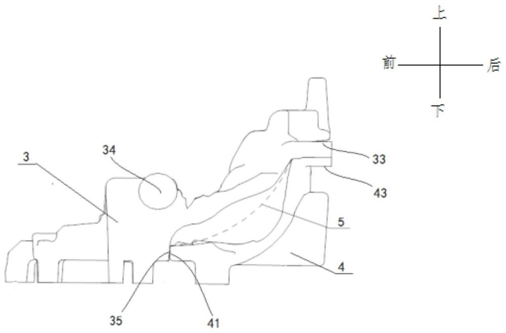
[0035] see image 3 , Figure 4 and Figure 5 , a cylinder head water jacket structure shown, including an upper water jacket 3 and a lower water jacket 4, characterized in that: the upper water jacket 3 is larger than the lower water jacket 4, and the rear part of the upper water jacket 3 is located at the lower water jacket 4 Above, the front lower end surface of the upper water jacket 3 is flush with the lower end surface of the lower water jacket 4 and both are positioned on the bottom plate of the cylinder head mold. Due to this positioning relationship and the entrance of molten aluminum below it, during casting, the upper and lower water jackets can be simultaneously affected by the buoyancy of the aluminum liquid, and are no longer affected by the superposition of the floating of the lower water jacket; because there are thicker and complete upper water jacke...


PUM


Abstract

The invention relates to a cylinder head water jacket structure, comprising an upper water jacket and a lower water jacket; the upper water jacket is larger than the lower water jacket, the rear of the upper water jacket is located above the lower water jacket, and the front of the upper water jacket is lower The end face is flush with the lower end face of the lower water jacket and both are positioned on the bottom plate of the cylinder head mold. The invention can not only solve the problem of precision deviation in the position of the water jacket during casting, but also solve the problem of insufficient cooling liquid in the connecting channel.

Description

technical field [0001] The invention relates to an automobile engine, in particular to a cylinder head water jacket structure. The water jacket structure is a sand core structure of the water jacket, which forms the inner cavity of the water jacket after casting. Background technique [0002] Integrated exhaust manifold technology is widely used in cylinder head products. CN 201610462501.0 discloses "A Cylinder Head Water Jacket Structure Covering Exhaust Manifold", see attached figure 1 and figure 2 . The interior of the cylinder head water jacket mentioned is a two-piece structure, which is divided into an upper water jacket 1 and a lower water jacket 2 from the middle, and the upper water jacket is slightly smaller than the lower water jacket. The two correspond to overlap through the upper right support point 11 and the lower right support point 21, the corresponding overlap between the upper left support point 14 and the lower left support point 24, the correspondi...

Claims


Application Information

Patent Timeline
Patent Type & Authority Patents(China)
IPC IPC(8): B22C9/10F02F1/16
CPCB22C9/10F02F1/16
Inventor 王锐
Owner CHONGQING CHANGAN AUTOMOBILE CO LTD
Why Eureka
Try Eureka