Stainless steel centrifugal pump shell forming method

A technology of stainless steel pump and centrifugal pump, applied in the direction of metal extrusion dies, etc., can solve the problems of complex forming die structure, high manufacturing cost, low strength, etc., to avoid thin wall or wall crack, low manufacturing cost and simple structure. Effect

Active Publication Date: 2006-01-04
南方中金环境股份有限公司
View PDF1 Cites 3 Cited by
  • Summary
  • Abstract
  • Description
  • Claims
  • Application Information

AI Technical Summary

Problems solved by technology

Its shortcomings: First, because the concave mold is a metal lotus-shaped split elastic combination, the steel plate located between the punch and the concave mold is in the stamping process of the top plate, the force on the steel plate is not only generated by the positive pressure of the punch , and the reverse pressure generated from the outer side of the elastic die and the matching top plate of the die, one positive and one reverse form multiple interactive bending forces, which are not only easy to generate during the forming process of the pump casing The concentration of hard force affects the service life of the pump casing, and a little carelessness can easily cause the pump casing to be brittle, which directly affects the molding quality and molding rate of the pump casing; secondly, the lack of a core mold in the molding mold causes the flow of the polyurethane rubber inner mold to be blocked, Part of the steel plate of the pump casing is overstretched, resulting in a decrease in strength and bearing capacity, which directly affects the service life of the pump casing; third, the forming die has a complex structure, high manufacturing costs, and high operation requirements. rod, otherwise it will not work

Method used


Image

  • Stainless steel centrifugal pump shell forming method
  • Stainless steel centrifugal pump shell forming method

Examples


Embodiment 1

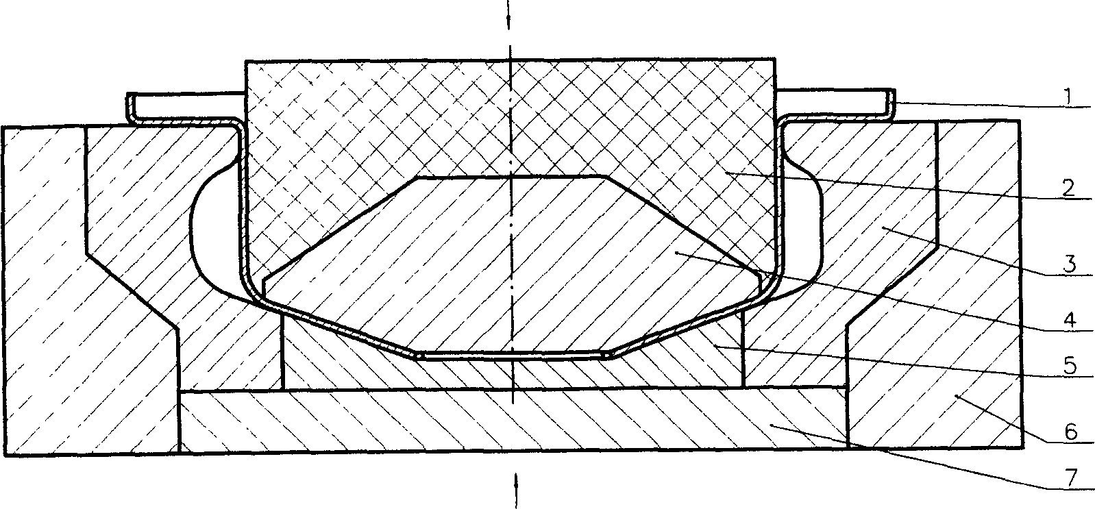
[0010] Embodiment 1: with reference to attached figure 1 . Stainless steel centrifugal pump casing forming method, the shape of the inner side of the outer mold is the same as that of the centrifugal pump casing, and the outer mold is composed of three forming modules to form a rigid mold frame. The shape of the inner side of the rigid mold frame is the same as that of the stainless steel centrifugal pump casing, that is, Say, the shape to be molded. The purpose of the steel mold frame being located in the steel sleeve of the outer mold is: first, the steel sleeve of the outer mold has an integral structure, and the three forming molds are combined to form a steel mold frame inside it, which is equal to the steel mold frame formed by combination; Because there is a top plate at the inner bottom of the steel sleeve of the outer mold, the top plate can eject the formed outer mold synchronously, and the outer mold is automatically separated after ejection, and the extruded stain...

Embodiment 2

[0011] Embodiment 2: with reference to attached figure 1 . The forming mold of stainless steel centrifugal pump casing is composed of outer mold steel sleeve 6, core mold 4, outer mold 3 and inner mold 2. The outer mold is composed of three forming molds to form a forming mold frame. The shape formed by the inner side of the forming mold frame is the same as that of a centrifugal pump. Shell shape and located in the outer mold steel sleeve 6, the core mold 4 is located at the bottom of the initially formed hat-shaped stainless steel pump casing 1 and the initially formed hat-shaped stainless steel pump casing 1 is located in the outer mold 3, and the inner mold 2 is located on the core mold 4 And in the initially formed hat-shaped stainless steel pump casing 1. The backing plate 5 in the outer mold 3 is positioned at the bottom in the outer mold frame, and its surface coincides with the bottom surface of the pump casing. The lower side of the mandrel 4 coincides with the bot...


PUM

PropertyMeasurementUnit
thicknessaaaaaaaaaa

Abstract

The present invention belongs to the field of centrifugal pump making technology. The forming process of centrifugal pump shell of stainless steel includes: adopting outer mold with steel mold frame comprising three combined forming mold blocks inside outer mold steel jacket; setting the core mold in the bottom and the inner mold of polyurethane material on the core mold; setting the initially formed cap-shaped stainless steel pump shell blank between the outer mold and the inner mold; applying the pressure head with oil press onto the inner mold slowly to make the inner mold extrude the stainless steel pump shell blank so as to form the stainless steel pump shell; pushing up the top board in the bottom of the outer mold steel jacket to open the three forming mold blocks and to take out the formed centrifugal pump shell of stainless steel.

Description

Technical field: [0001] The invention relates to a forming method of a stainless steel centrifugal pump shell, which belongs to the field of centrifugal pump manufacturing. Background technique: [0002] Authorized announcement number CN1045811C, name "stamping and forming centrifugal pump and its manufacturing method", between the pump casing and the impeller, stamped by the expansion forming method into a gradually increasing cross-section along the direction of liquid flow, asymmetrical and uneven on the circumference The volute is in the shape of a volute, and the outlet of the volute communicates with the outlet bend neck of the variable-diameter elliptical section. Using the metal lotus-shaped split elastic combination concave die and polyurethane rubber as the internal punch, the metal plate with a thickness of 0.5-5.0 mm is punched and formed many times under normal temperature and high pressure. Its shortcomings: First, because the concave mold is a metal lotus-sha...

Claims


Application Information

Patent Timeline
Patent Type & Authority Applications(China)
IPC IPC(8): B21C23/14B21C25/02
Inventor 赵才甫沈国连赵国忠
Owner 南方中金环境股份有限公司
Why Eureka
Try Eureka