Direct-current (DC) solid-state relay

A technology of relays and resistors, applied in the field of relays, can solve the problems of unstable operation, reduced reliability, and malfunctions of relays, and achieve the effect of preventing critical jitter and high working stability

Inactive Publication Date: 2012-07-04
HOHAI UNIV
View PDF0 Cites 1 Cited by
  • Summary
  • Abstract
  • Description
  • Claims
  • Application Information

AI Technical Summary

Problems solved by technology

[0003] The existing solid state relays have approximately the same critical voltage for turn-on and turn-off, and the action is inaccurate near the critical voltage, which is likely to cause misoperation
At the same time, the output of the relay is often affected by the size of the load. For a circuit with a changing load, the output voltage of the DC solid state relay will drift, resulting in unstable operation of the relay and reduced reliability.

Method used


Image

  • Direct-current (DC) solid-state relay
  • Direct-current (DC) solid-state relay
  • Direct-current (DC) solid-state relay

Examples


Embodiment Construction

[0012] The present invention will be further described below in conjunction with accompanying drawing.

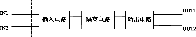
[0013] Such as figure 1 As shown, the structure of the DC solid state relay of the present invention is composed of an input circuit, an isolation circuit and an output circuit connected in sequence, the IN1 end and the IN2 end of the input circuit are used as the input end of the relay, and the OUT1 end and OUT2 end of the output circuit are used as the output of the relay end.

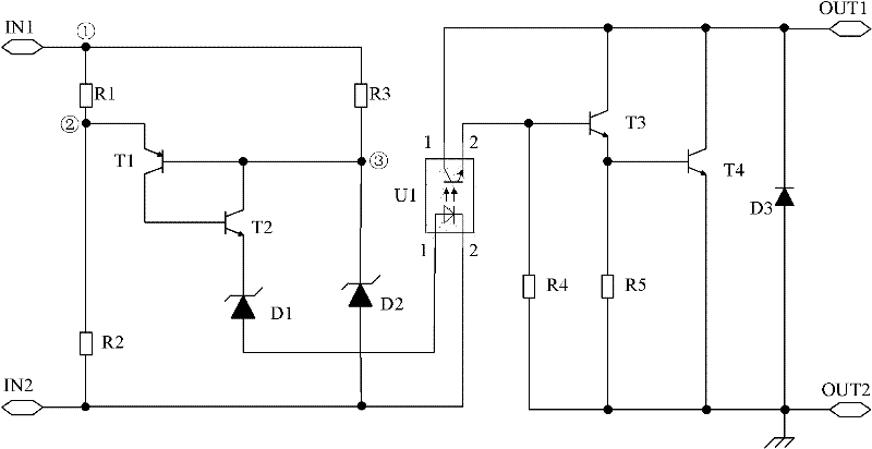
[0014] The concrete circuit structure of relay of the present invention is as figure 2 As shown, the input circuit includes first to third resistors R1~R3, first and second switch tubes T1, T2, and first and second diodes D1, D2, and the isolation circuit is an optocoupler U1, wherein: the connection point between one end of the first resistor R1 and one end of the third resistor R3 constitutes the IN1 end of the input circuit, and the other end of the first resistor R1 is respectively connecte...


PUM


Abstract

The invention discloses a direct-current (DC) solid-state relay, and belongs to the relay field. The relay is composed of an input circuit, an isolating circuit and an output circuit which are sequentially connected together, wherein, the input circuit and the output circuit are respectively composed of a resistor, a switching tube and a diode, and a photoelectric coupler is adopted in the isolating circuit. The DC solid-state relay has the advantages that a positive feedback circuit is introduced into the input circuit so that the break-over voltage value and the cut-off voltage value of therelay are separated from each other and a certain margin is reserved; the relay has hysteresis characteristic, thus avoiding a critical jitter phenomenon; relay output is not affected by load, and ports are relatively independent; and the relay can accurately work in the case of an operation critical value, thus improving the operating stability.

Description

technical field [0001] The invention relates to a solid-state relay, in particular to a DC solid-state relay with hysteresis characteristics, and belongs to the field of relays. Background technique [0002] In the existing relay technology, most of the DC relays are electromagnetic relays. This type of relays generally attracts the armature through the magnetic effect generated by the coil to achieve the function of conducting and disconnecting the circuit. Since this electromagnetic relay adopts the electromagnetic principle, it is easily disturbed by the outside world. In addition, long-term use of the contacts of this relay will inevitably cause wear, especially in circuits with large currents. The arc formed by long-term conduction and disconnection will oxidize the contacts of the relay and affect the conduction and shutdown capabilities, thereby affecting To the proper effect and function of the circuit. Relatively speaking, because it has no movable mechanical cont...

Claims


Application Information

Patent Timeline
Patent Type & Authority Patents(China)
IPC IPC(8): H03K17/785
Inventor 陈谦鞠平黄攀卞海浪韩敬东金宇清
Owner HOHAI UNIV
Why Eureka
Try Eureka