Arm mechanism and vacuum robot with the mechanism

A technology of arm mechanism and robot, which is applied in the field of robotics, can solve problems such as excessive increase of arm base, increase of arm mass, limitation of arm telescopic range, etc., and achieve good effects of maintaining straight line trajectory, improving transmission rigidity, and safe wiring

Inactive Publication Date: 2013-09-04
YASKAWA DENKI KK
View PDF2 Cites 0 Cited by
  • Summary
  • Abstract
  • Description
  • Claims
  • Application Information

AI Technical Summary

Problems solved by technology

Therefore, when the arm stretches, it needs to be moved within the range where the first arm and the first link do not interfere with each other, and there are cases where the stretching range of the arm is limited.
Since it is necessary to extend the telescopic range of the arms, it is necessary to arrange the distance between the axes of each arm and the distance between the axes of each link to be relatively long, so there is a problem that the mass of each arm increases, or due to the increase of the first arm and the first The inter-axis distance between the connecting rods has to make the arm base excessively large, etc.

Method used


Image

  • Arm mechanism and vacuum robot with the mechanism
  • Arm mechanism and vacuum robot with the mechanism
  • Arm mechanism and vacuum robot with the mechanism

Examples


Embodiment 1

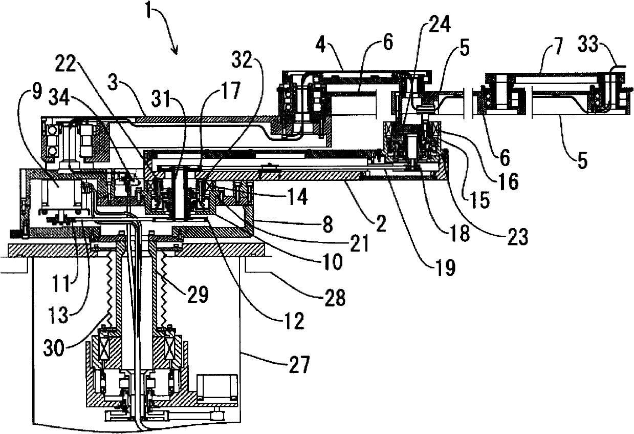
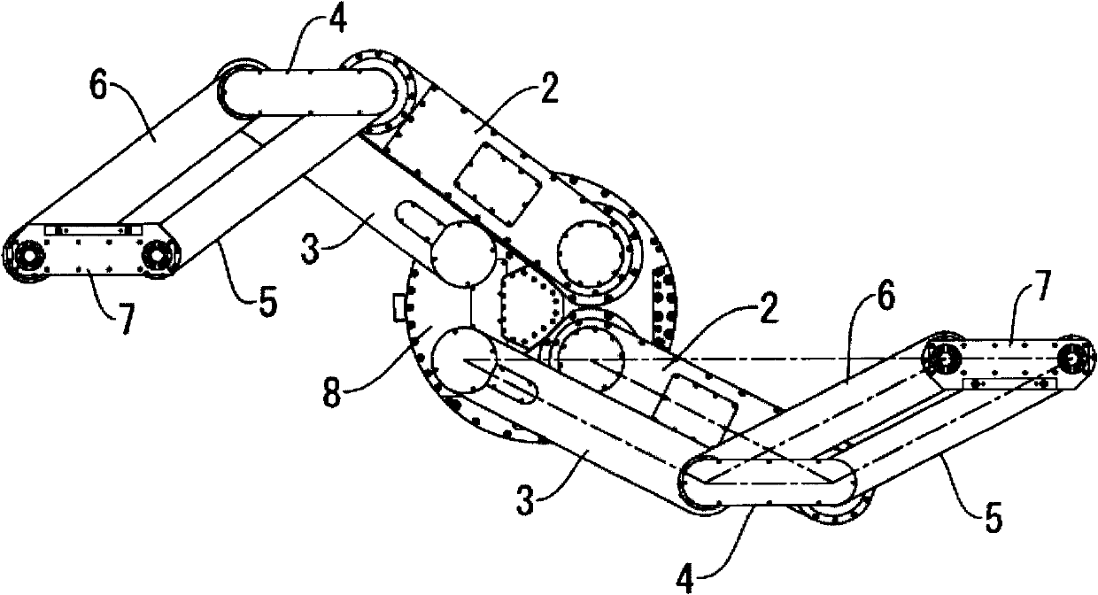
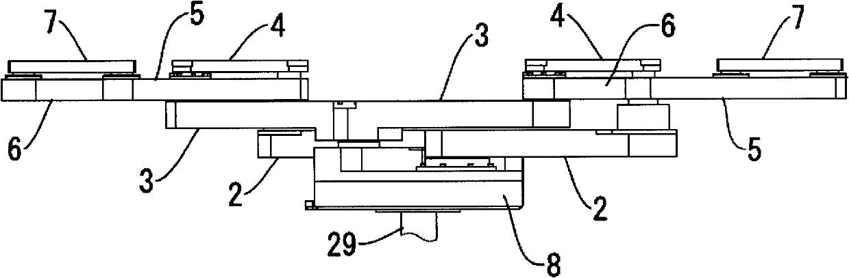
[0039] figure 1 One embodiment of the present invention is shown, and it is a side sectional view mainly showing an arm part of a vacuum robot. and, figure 2 yes figure 1 top view. and, image 3 yes figure 1 side view of the exterior. Such as figure 2 As shown, in this embodiment, a so-called dual-arm vacuum robot equipped with two arms is shown, but as described below, there is no problem even with a vacuum robot with one arm. In addition, since the two arms have the same structure, the following basis figure 1 and figure 2 Only the structure of any one arm is described.

[0040] The arm generally has: the first arm 2, which can rotate on the arm base 8 described later; the second arm 5, which can rotate on the front end of the first arm 2; the first link 3, which can be rotated on the arm base 8 Rotate upward, its front end is rotatably connected with the front end of the first arm 2 through the first connecting rod 4; the base end of the second connecting rod 6...


PUM


Abstract

A first decelerator is placed in an arm base such that a lower end of a decelerator shaft is bared in the arm base. A first arm has a hermetic space which becomes equal in pressure to a hermetic space of the arm base when an upper end of the hollow decelerator shaft is inserted thereinto, and is secured to a first decelerator output shaft. A second decelerator is placed on a distal end of the first arm, and has an input shaft connected to the decelerator shaft. A second arm is secured to an output shaft of the second decelerator, and has no hermetic space formed therein. A link mechanism follows the first and second arms.

Description

technical field [0001] The invention relates to a robot for transferring wafers, glass and other substrates in vacuum, especially the structure of the robot arm. The vacuum mentioned here means the state of space after the atmospheric pressure is depressurized by a pump or the like, for example. Background technique [0002] For example, patent document 1 etc. are known about the arm structure of the robot which conveys a substrate. In Patent Document 1, in order to move the robot arm and hand, a transmission mechanism such as a motor, a speed reducer, and a timing belt is arranged inside the arm. On the other hand, this type of robot is installed in a vacuum container depressurized from atmospheric pressure, and is used to transport substrates such as wafers and glass. A robot placed in a vacuum container is called a vacuum robot. In order not to destroy the vacuum environment in the vacuum container, the vacuum robot needs to operate while isolating the atmospheric pres...

Claims


Application Information

Patent Timeline
Patent Type & Authority Patents(China)
IPC IPC(8): B25J9/06B25J18/00H01L21/677
CPCB25J9/044B25J9/1065H01L21/67742B25J9/042Y10T74/20311Y10T74/20305B25J11/0095H01L21/68707Y10S414/141
Inventor 多良文宏古川伸征大仁健辅
Owner YASKAWA DENKI KK
Why Eureka
Try Eureka