Mobile rocker arm shaft type variable valve timing mechanism

A valve timing and rocker shaft technology, applied in combustion engines, engine control, engine components, etc., can solve the problems of increased manufacturing costs, complex and bulky variable valve drive mechanisms and control mechanisms, etc., to improve power performance, improve Fuel economy and emissions performance, the effect of reducing pumping losses

Active Publication Date: 2011-05-25
SHANDONG UNIV
View PDF6 Cites 4 Cited by
  • Summary
  • Abstract
  • Description
  • Claims
  • Application Information

AI Technical Summary

Problems solved by technology

If the traditional hydraulically driven variable valve mechanism is used, in addition to changing the structure of the main parts of the valve mechanism, an additional hydraulic drive mechanism is required, which makes the drive mechanism and

Method used


Image

  • Mobile rocker arm shaft type variable valve timing mechanism
  • Mobile rocker arm shaft type variable valve timing mechanism
  • Mobile rocker arm shaft type variable valve timing mechanism

Examples


Embodiment 1

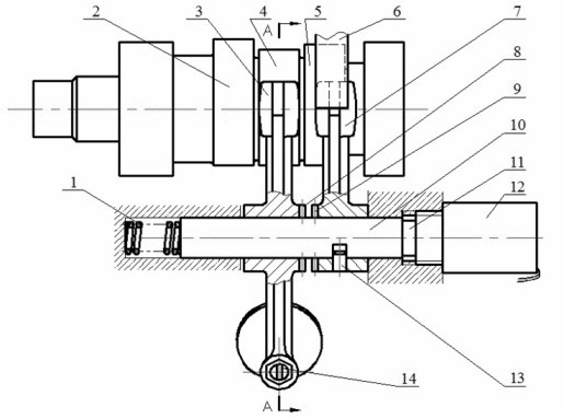
[0018] exist figure 1 and figure 2 The interrelationships among the components are as follows: the low-speed intake cam 4 drives the low-speed rocker arm 3, the high-speed intake cam 5 drives the high-speed rocker arm 7, and the leaf spring 6 exerts a certain elastic force on the high-speed rocker arm 7, so that the high-speed rocker arm 7 is always in contact with the high-speed intake cam 5; the low-speed rocker arm 3 and the high-speed rocker arm 7 can swing around the intake rocker shaft 10 driven by their respective cams, and the high-speed rocker arm 7 is on the shaft of the intake rocker shaft 10 The direction position is determined by the axial positioning pin 13; the electromagnet 12 is the rocker shaft driving mechanism, and the electromagnetic force generated by it pushes the armature 11 to drive the intake rocker shaft 10 to move to the left; the return spring 1 is in a compressed state; the low-speed rocker The axial position of 3 is fixed, its upper end is in c...

Embodiment 2

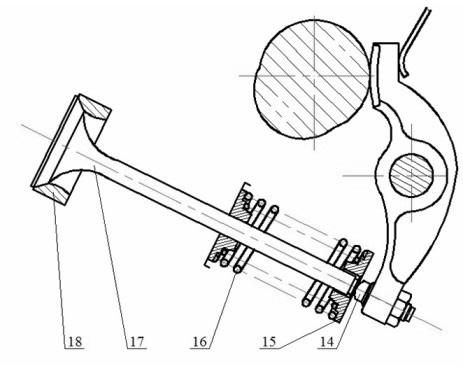
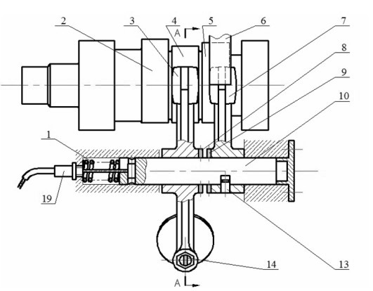
[0024] exist image 3 Among them, the tension cable system 19 is a rocker shaft drive mechanism. By manually applying a certain force, the ropes in the rope system 19 are in a tensioned state, and the rope system 19 tightens the rocker shaft 10 and drives the high-speed rocker 7 to move to the left, so that the low-speed rocker 3 and the high-speed rocker 7 are combined. , the working cam is switched to the high-speed intake cam 5. When the rope system 19 was in a loose state, the return spring 1 made the rocker shaft 10 drive the high-speed rocker 7 to move to the right, the low-speed rocker 3 and the high-speed rocker 7 were separated, and the working cam was switched to the low-speed intake cam 4. This enables variable intake valve timing.

[0025] exist figure 1 Among them, the low-speed rocker arm 3 and the high-speed rocker arm 7 are connected together through their end face coupling teeth 8 and 9; the low-speed rocker arm and the high-speed rocker arm can also h...


PUM


Abstract

The invention relates to a mobile rocker arm shaft type variable valve timing mechanism of a single-cylinder internal combustion engine. The mechanism is structurally characterized in that: a rocker arm shaft and a high-speed rocker arm can move together along the axis of the rocker arm shaft; and the high-speed rocker arm and a low-speed rocker arm are combined or separated. When the high-speed rocker arm and the low-speed rocker arm are in a combination state, a high-speed cam drives the high-speed rocker arm and drives the low-speed rocker arm to swing together, and the high-speed cam drives a valve to open and close, so the mechanism is suitable for the high-speed and large-load working conditions of the internal combustion engine; and when the high-speed rocker arm and the low-speed rocker arm are in a separation state, a low-speed cam drives the low-speed rocker arm and the valve to open and close, so the mechanism is suitable for the low-speed working conditions and small-load working conditions of a gasoline engine. The variable valve timing mechanism has simple structure, can obviously enhance the dynamic property and economy of the internal combustion engine, and is particularly suitable for a single overhead camshaft type single-cylinder four-stroke internal combustion engine.

Description

technical field [0001] The invention relates to a valve mechanism of an internal combustion engine, in particular to an overhead camshaft type single-cylinder internal combustion engine valve mechanism with a rocker arm. Background technique [0002] Variable Valve Timing (VVT for short) is one of the main ways for internal combustion engines to save energy and reduce emissions. At present, the new gasoline engine products released by major automobile companies all use the variable valve technology as one of the main technical symbols of the new gasoline engine. Although there are many forms of variable valve, the variable valve mechanism that can be widely used in gasoline engines is the variable valve mechanism that changes the cam profile. However, due to the limitation of manufacturing cost and mechanism complexity, there is no variable valve mechanism and its application examples suitable for small and medium-displacement single-cylinder four-stroke gasoline engines at...

Claims


Application Information

Patent Timeline
IPC IPC(8): F01L1/34F02D13/02
CPCY02T10/18Y02T10/12
Inventor 谢宗法王志明刘永田
Owner SHANDONG UNIV
Why Eureka
Try Eureka