
Portable electroscope

An electroscope and portable technology, applied in the direction of indicating the existence of current/voltage, can solve the problems of affecting the electroscope effect, inconvenient to carry, tedious preparation work, etc., to shorten the detection time and personnel, reduce the detection time and personnel, Reduce the effect of cooperating staff

Inactive Publication Date: 2011-05-25
宁夏电力公司超高压分公司
View PDF5 Cites 4 Cited by
  • Summary
  • Abstract
  • Description
  • Claims
  • Application Information

AI Technical Summary

Problems solved by technology

At present, the structural length of 330kV and above voltage level has reached 4.5-8 meters, so the length of the insulating rod will reach 5-9 meters, which brings the following problems to the measurement: 1. Inconvenient to carry
When measuring, it is necessary to carry pulleys, insulating rods, insulating ropes and other appliances; 2. The preparation work before the test is cumbersome, labor-intensive, and takes a long time
The personnel who go up to the tower pole for measurement need to carry pulleys, insulating ropes, etc. After reaching the top of the tower, they need to install pulleys, put down the insulating ropes, and the ground cooperating personnel will transport the insulating rods to the top of the tower before the measurement can be carried out, which is time-consuming and laborious; 3. Difficult to measure and low in security
Since the retractable insulating rod is very long, the swing is relatively large during measurement, which affects the efficiency of the electric test on the one hand, and brings potential safety hazards on the other hand

Method used


Image

  • Portable electroscope
  • Portable electroscope
  • Portable electroscope

Examples


Embodiment Construction

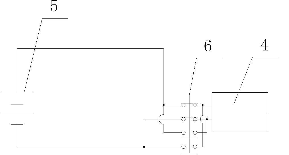
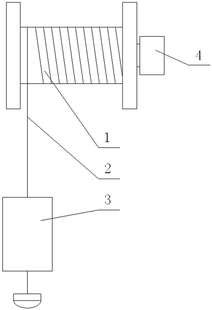
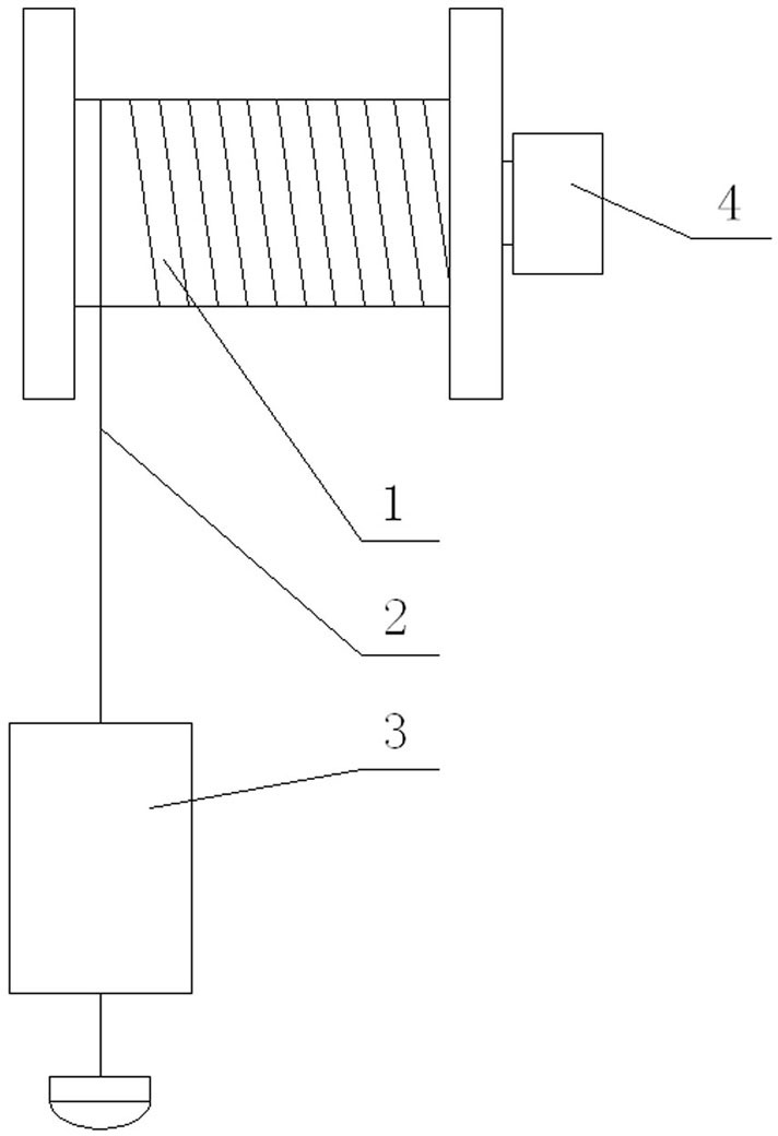
[0015] Such as figure 1 , 2 As shown, the contact electroscope 3 is connected with the insulating rope 2, the other end of the insulating rope is fixed and wound on the reel 1, the reel is connected with the output shaft of the motor 4, and the battery 5 is electrically connected with the motor through the control switch 6. In order to be easy to carry, the reel, battery and motor can be fixedly installed in a box body. There is an opening on the box body for the extension of the insulating rope. The transmission line to be tested is in contact with the contact electroscope with a buzzer device, and the electroscope head of the contact electroscope is equipped with a magnet.

[0016] During the electric inspection, the surveyor carries the electric inspection device directly to the top of the tower, and after taking safety protection measures, presses the control switch 6 installed on the surface of the box body, and the motor drives the reel to rotate, so that the roller ins...


PUM


Abstract

The present invention relates to a circuit detection device, in particular to a portable electroscope, which comprises a contact electroscope. The portable electroscope is characterized in that the contact electroscope is connected with an insulating rope, the other end of the insulating rope is fixedly wound on a rolling wheel, and the rolling wheel is connected with a retractable device capable of driving the rolling wheel to rotate forwards or backwards. Since the insulating rope is used instead of an insulating rod in the technical scheme, the present invention has the following advantages that: 1, the weight in the detection process is greatly reduced; 2, no installation of pulleys or cooperation of ground staff is needed, and thus the detection time is shortened and the number of the detection personnel is reduced; and 3, since the existing power transmission line adopts an aluminum stranded wire with a steel wire in the middle, and the power detection head of the electroscope is provided with a high-performance magnet, the contact electroscope can be accurately contacted with the power transmission line to be connected with the power transmission line for measurement. Therefore, the device is easy to carry and measure, effectively improves the measurement efficiency, reduces the required personnel, and enhances the detection safety.

Description

technical field [0001] The invention relates to a device for circuit detection, especially a portable electroscope. Background technique [0002] According to Article 3.3.1 of the "State Grid Corporation Electric Power Safety Work Regulations (Line Part)", before installing the ground wire in the working section of the power outage line, the electricity should be checked first to verify that the line has no voltage. For electrical inspection, a qualified contact electroscope with corresponding voltage level should be used. At present, the electroscopes commonly used on high-voltage transmission lines are of the pull-out type, that is, according to the test voltage level, the contact electroscope of the corresponding level is installed on the head of the retractable insulating rod for measurement. When measuring, the surveyors first go up to the cross arm on the top of the tower pole, fix the pulley on the cross arm, and transport the electroscope and insulating rod to the t...

Claims


Application Information

Patent Timeline
IPC IPC(8): G01R19/145
Inventor 张志荣郑仟谢贵文陈海军
Owner 宁夏电力公司超高压分公司
Learn More