Subwavelength binary diffraction grating-based wavelength separator

A wavelength separation, binary diffraction technology, applied in diffraction gratings, light guides, optics, etc., can solve the problems of large loss of multiple reflection light, numerous components, difficult angle adjustment, etc., to achieve a simple and mature manufacturing process, principles and processes. Simple, low-cost effects

Inactive Publication Date: 2011-05-25
BEIJING JIAOTONG UNIV
View PDF4 Cites 10 Cited by
  • Summary
  • Abstract
  • Description
  • Claims
  • Application Information

AI Technical Summary

Problems solved by technology

For example, refer to [Chinese patent 200380102389 Manufacturing method of optical multiplexer and demultiplexer and optical multiplexer and demultiplexer] is to use the multiple reflections of the plane mirror layer and the filter layer to demultiplex the optical signals of multiple wavelength regions into each wavelength region, this method The disadvantage is that there are many components, the angle between each other is difficult to adjust, and the loss of multiple reflection light is large

Method used


Image

  • Subwavelength binary diffraction grating-based wavelength separator
  • Subwavelength binary diffraction grating-based wavelength separator
  • Subwavelength binary diffraction grating-based wavelength separator

Examples


Embodiment 1

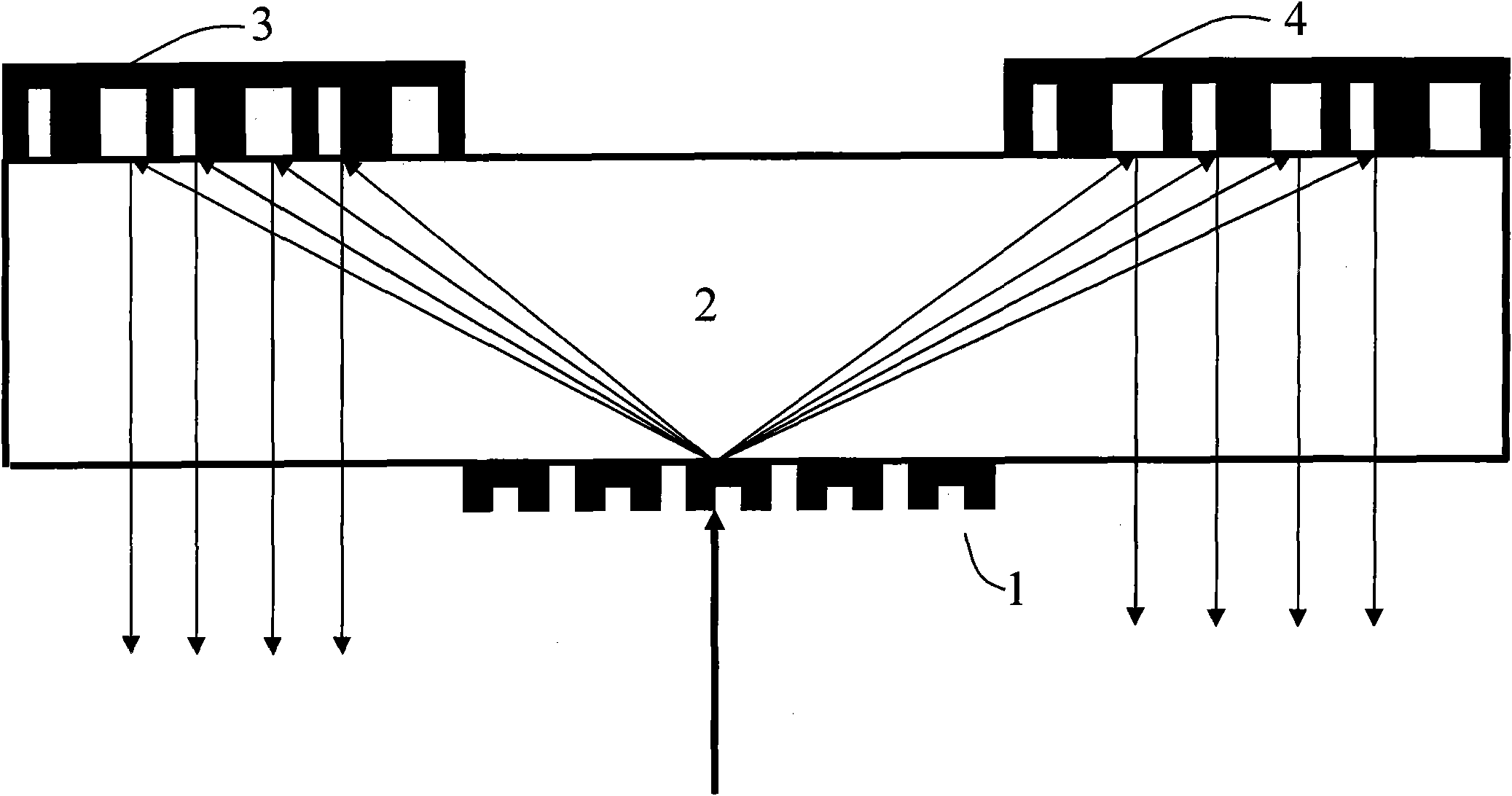
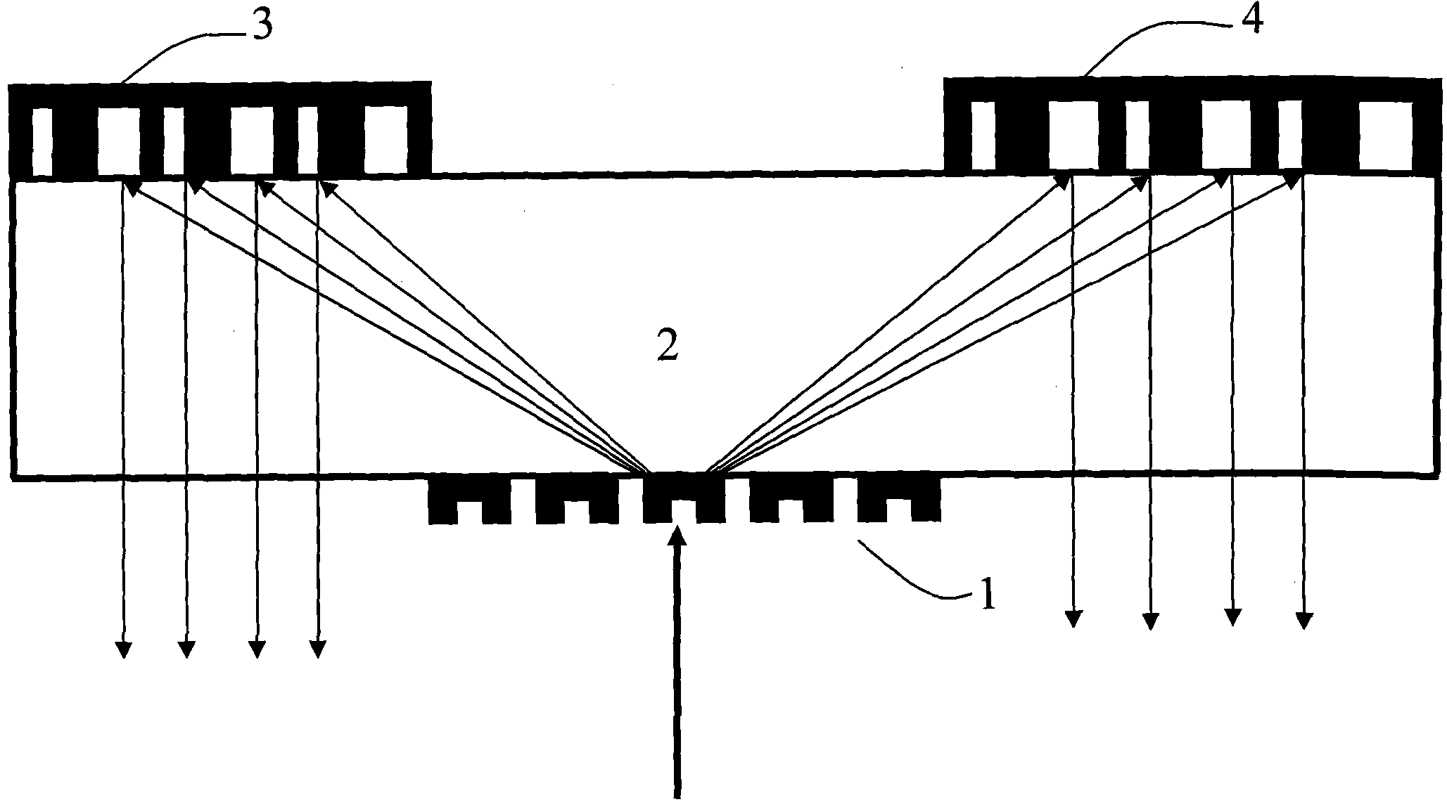
[0023] figure 1 Shown is the experimental setup of an optical splitter / combiner realized by a subwavelength binary transmission grating, two subwavelength binary reflection gratings and a pure quartz plate. The components used in the device include: a sub-wavelength binary transmission grating 1 , a pure quartz plate 2 , a first sub-wavelength binary reflection grating 3 , and a second sub-wavelength binary reflection grating 4 . Among them, the structure of the subwavelength binary transmission grating 1 is concave, and the material is SI y N x ; The first sub-wavelength binary reflective grating 3 is the same as the second sub-wavelength binary reflective grating 4, both of which are bow-shaped in structure and made of gold or silver.

[0024] The position between the above devices constituting the device: the subwavelength binary transmission grating 1 is adhered to the lower end surface of the pure quartz plate 2 through the refractive index matching liquid, the first su...

Embodiment 2

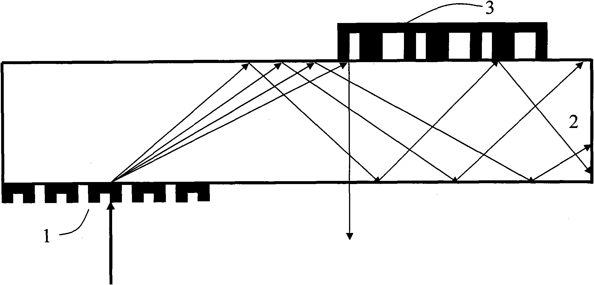
[0032] figure 2 Shown is the experimental setup of an optical filter realized by a combination of a subwavelength binary transmission grating, a subwavelength binary reflection grating and a pure quartz plate. The components used in the device are: a sub-wavelength binary transmission grating 1 , a pure quartz plate 2 , and a first sub-wavelength binary reflection grating 3 . Among them, the structure of the subwavelength binary transmission grating 1 is concave, and the material is SI y N x ; The structure of the first subwavelength binary reflective grating 3 is bow-shaped, and the material is gold or silver.

[0033] The position between the above devices constituting the device: the sub-wavelength binary transmission grating 1 is adhered to the lower end surface of the pure quartz plate 2 through the refractive index matching liquid, and the first sub-wavelength binary reflection grating 3 is adhered to through the refractive index matching liquid On the upper end surf...


PUM


Abstract

The invention discloses a subwavelength binary diffraction grating-based method for implementing a wavelength separator. The wavelength separator consists of three subwavelength binary diffraction gratings and a pure quartz glass flake, wherein one subwavelength binary transmission grating with a concave structure is made of SIyNx and arranged on the lower end face of the pure quartz flake; and the other two subwavelength binary reflection gratings with bow-shaped structures are made of gold or silver, arranged on the upper end face of the pure quartz flake, and positioned on the left and the right of the subwavelength binary transmission grating in equal distance respectively so as to form an inverted triangle with the subwavelength binary transmission grating. The subwavelength binary diffraction grating device required by the invention has the advantages of simple and mature manufacture process and low manufacture cost, and the principle and process of the whole wavelength separation are simple and practical and can be instantly applied practically to generate economical benefit.

Description

technical field [0001] The invention belongs to the technical field of optical waveguide devices and can be used to manufacture simple and efficient optical splitter / combiner and optical filter. Background technique [0002] Wave splitter / multiplexer is a key device in wavelength division multiplexing (DWDM) system and one of the hotspots in the research of integrated optical devices. Various wave splitters / multiplexers of different materials and principles have been designed and manufactured. With the in-depth research and application development of wavelength division multiplexing systems and integrated optical devices, the cost and volume of wave splitters / multiplexers have attracted more and more attention. [0003] Subwavelength grating components have been extensively researched and applied, and the characteristics of low production cost and tiny structure make various laboratories and institutions have no less interest in subwavelength gratings. Subwavelength gratin...

Claims


Application Information

Patent Timeline
Patent Type & Authority Applications(China)
IPC IPC(8): G02B6/293G02B5/18
Inventor 张帆袁博刘楚温晓东宁提纲
Owner BEIJING JIAOTONG UNIV
Why Eureka
Try Eureka