Micro linear vibration motor
A linear vibration, motor technology, applied in the direction of electric components, casings/covers/supports, electrical components, etc., can solve the problems of shortening motor life, not getting large-scale use, wearing brushes, etc., to facilitate accurate positioning , Reduce the adverse effect of hindering the vibration of the elastic connection, the effect of excellent elasticity and strength
- Summary
- Abstract
- Description
- Claims
- Application Information
AI Technical Summary
Problems solved by technology
Method used
Image

Examples
Embodiment 1
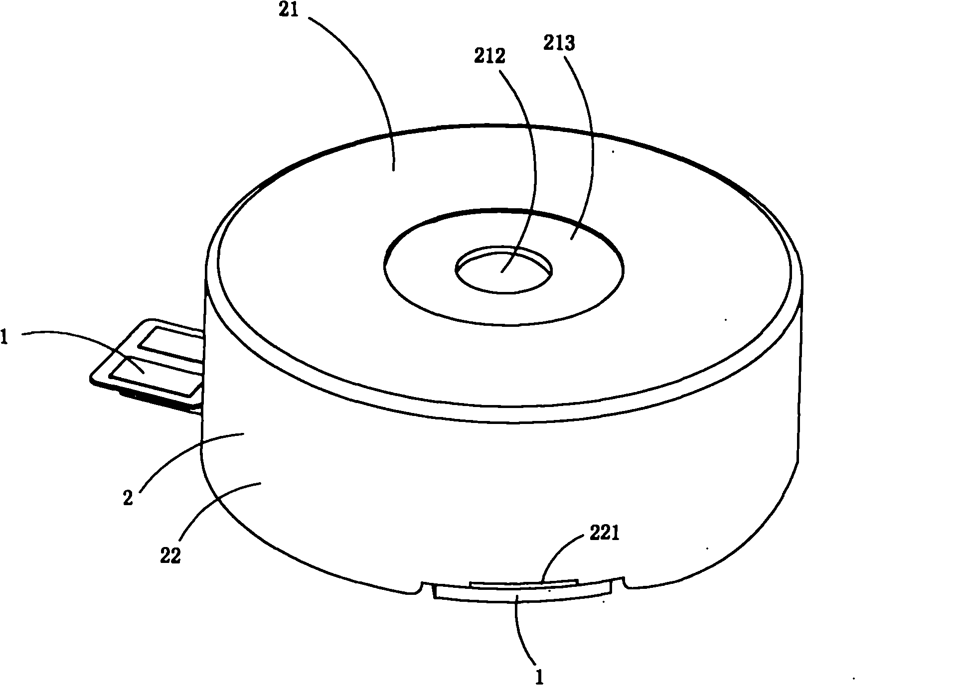
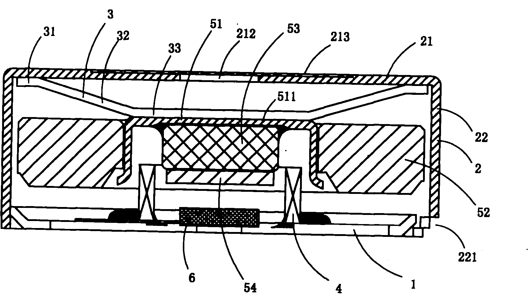
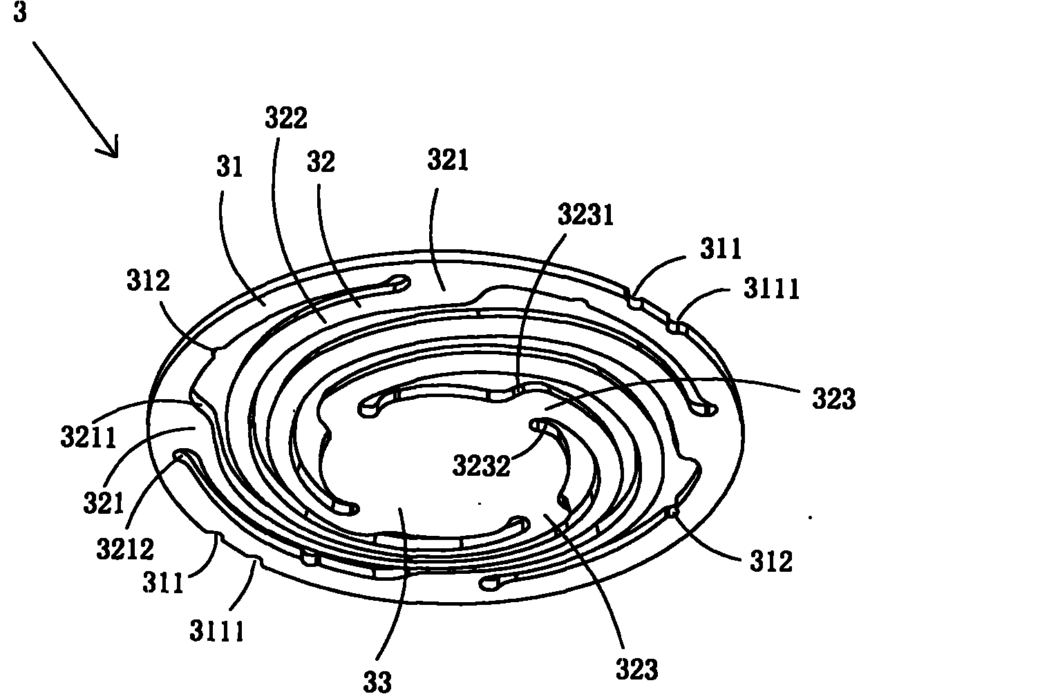
[0031] Figure 1 to Figure 6 A first embodiment of the invention is shown, in which figure 1 It is a schematic diagram of a three-dimensional structure of the first structure of the present invention; figure 2 for figure 1 The half-section view of the miniature linear vibrating motor shown; image 3 for figure 1 A schematic diagram of a three-dimensional structure of the return elastic member in the micro linear vibration motor shown; Figure 4 for image 3 A front view of the reset elastic member shown; Figure 5 for figure 1 A schematic diagram of a three-dimensional structure of the housing in the miniature linear vibration motor shown; Figure 6 for Figure 5 A front view of the enclosure shown.
[0032] This embodiment is a kind of miniature linear vibration motor used in mobile phones, see Figure 1 to Figure 4 , including a base 1, a casing 2 fixed on the base 1, a reset elastic member 3 arranged on the top wall 21 of the casing 2, a coil 4, a vibrator assembly...
Embodiment 2
[0049] Figure 7 It is a half-sectional view of the second structure of the present invention, showing the second specific implementation manner of the present invention.
[0050] This embodiment is basically the same as Embodiment 1, the difference is: see Figure 7 , the center of the lower surface of the top wall 21 of the casing 2 is provided with a limiting groove 211, and the fixing part 31 of the reset elastic member 3 is provided with an upwardly protruding limiting protruding ring 313, and the limiting protruding ring 313 Cooperating with the shape of the limiting groove 211 , the limiting protruding ring 313 of the restoring elastic member 3 is located in the limiting groove 211 .
[0051] This embodiment can accurately and concentrically position the reset elastic member and the casing, so that the installation and fixing process of the reset elastic member is simpler and quicker, and has more reliable and stable elastic recovery performance.
PUM
 Abstract
Description
Claims
Application Information
 - R&D
- Intellectual Property
- Life Sciences
- Materials
- Tech Scout
- Unparalleled Data Quality
- Higher Quality Content
- 60% Fewer Hallucinations
Browse by: Latest US Patents, China's latest patents, Technical Efficacy Thesaurus, Application Domain, Technology Topic, Popular Technical Reports.
© 2025 PatSnap. All rights reserved.Legal|Privacy policy|Modern Slavery Act Transparency Statement|Sitemap|About US| Contact US: help@patsnap.com