
Medium-high voltage frequency converter with integrated structure

A medium and high voltage frequency converter and frequency converter technology, which is applied in the direction of output power conversion devices, electrical components, cooling/ventilation/heating renovation, etc. Production reserve, simple and convenient connection, and the effect of reducing floor space

Active Publication Date: 2011-05-25
WOLONG ELECTRIC GRP LIAONING RONGXIN ELECTRIC TRANSMISSION CO LTD +1
View PDF4 Cites 14 Cited by
  • Summary
  • Abstract
  • Description
  • Claims
  • Application Information

AI Technical Summary

Problems solved by technology

[0002] In the prior art, the switching cabinet, control cabinet, transformer cabinet and frequency conversion power unit cabinet of the frequency converter are all independent cabinets, and their spatial arrangement is arranged in sequence; the switching cabinet, the control cabinet and the transformer cabinet are respectively connected by cables and control lines , the frequency conversion power unit cabinet is connected to the control cabinet and the transformer cabinet respectively through control lines and cables. Due to the layout of the existing structure, the connection between each other is long and intertwined, which is not convenient for assembly and maintenance; the transformer cabinet and the frequency conversion power unit cabinet Separately set the fans for heat dissipation, the number of fans is large, and the power consumption is high; moreover, the layout of the cabinets arranged in sequence makes the overall structure of the inverter large in size, large in floor space, high in cost, and low in power density

Method used


Image

  • Medium-high voltage frequency converter with integrated structure
  • Medium-high voltage frequency converter with integrated structure
  • Medium-high voltage frequency converter with integrated structure

Examples


Embodiment Construction

[0018] The technical content of the present invention will be further described in detail below in conjunction with the accompanying drawings.

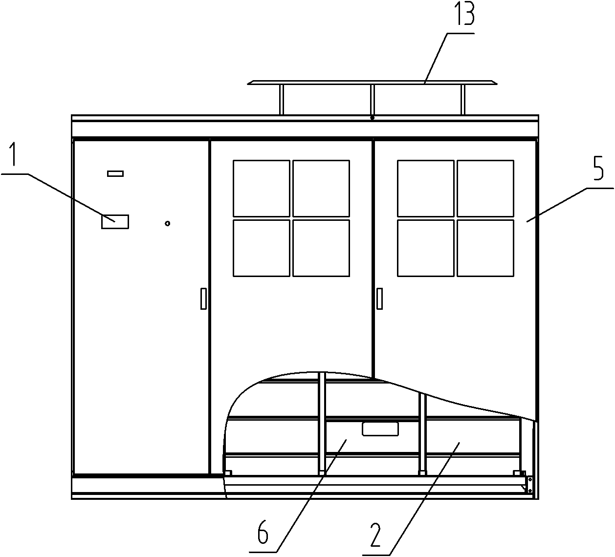
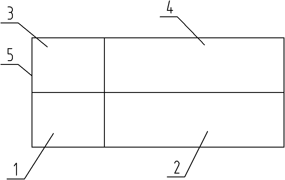
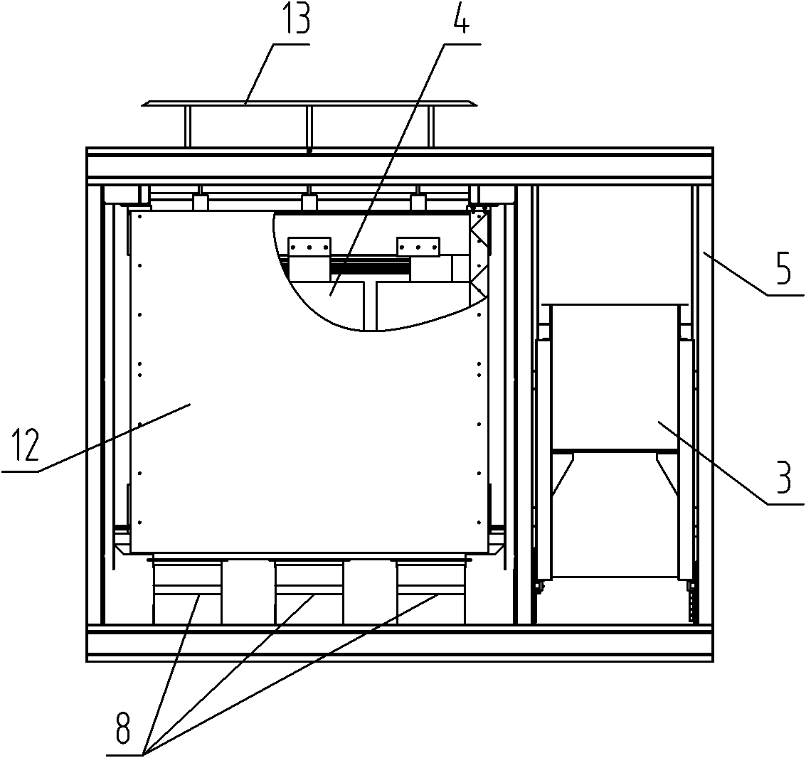
[0019] See figure 1 , figure 2 , image 3 , is a structural schematic diagram of an embodiment of a medium and high voltage inverter with an integrated structure of the present invention, including a control unit 1, a frequency conversion power unit 2, a switching unit 3, and a transformer unit 4. The control unit 1 and the frequency conversion power unit 2 are located in the inverter cabinet 5 The front is arranged left and right; the switch unit 3 and the transformer unit 4 are located at the rear of the inverter cabinet 5, and the controller unit 1 and the frequency conversion power unit 2 form a square layout with an integrated front and rear row.

[0020] The switching unit 3 and the transformer unit 4 are connected by cables, and the frequency conversion power unit 2 and the transformer unit 4 are connected by plugs and short...


PUM


Abstract

The invention relates to a medium-high voltage frequency converter with an integrated structure, which comprises a control unit, a variable-frequency power unit, a switching unit and a transformer unit, and is characterized in that the variable-frequency power unit and the transformer unit are arranged front and back in a frequency converter cabinet. A series ventilation cooling system is arranged between the variable-frequency power unit and the transformer unit. The variable-frequency power unit adopts a drawer-type structure and comprises a plurality of power units which are vertically arranged with each column corresponding to a phase. Compared with the prior art, the medium-high voltage frequency converter has the advantages that: 1) the control unit, the variable-frequency power unit, the switching unit and the transformer unit are formed in an integrated structure, so the structure is impact and the cost is low; 2) the variable-frequency power unit is assembled in a vertical manner by adopting a drawer-type structure, so floor area is reduced; 3) the installation in a quick plug-pull connection manner of the power units contributes to the production storage, installation, expansion and transportation of the power units; and 4) series ventilation is adopted between the transformer unit and the variable-frequency power unit.

Description

technical field [0001] The invention relates to the field of medium and high voltage frequency converters, in particular to a medium and high voltage frequency converter with an integrated structure. Background technique [0002] In the prior art, the switching cabinet, control cabinet, transformer cabinet and frequency conversion power unit cabinet of the frequency converter are all independent cabinets, and their spatial arrangement is arranged in sequence; the switching cabinet, the control cabinet and the transformer cabinet are respectively connected by cables and control lines , the frequency conversion power unit cabinet is connected to the control cabinet and the transformer cabinet respectively through control lines and cables. Due to the layout of the existing structure, the connection between each other is long and intertwined, which is not convenient for assembly and maintenance; the transformer cabinet and the frequency conversion power unit cabinet The fan is i...

Claims


Application Information

Patent Timeline
IPC IPC(8): H02M1/00H05K7/20
Inventor 张其生郭度厚
Owner WOLONG ELECTRIC GRP LIAONING RONGXIN ELECTRIC TRANSMISSION CO LTD
Learn More