Hysteresis comparator
A hysteresis comparator, amplifier technology, applied in multiple input and output pulse circuits and other directions, can solve the problems of low precision and low practicability
- Summary
- Abstract
- Description
- Claims
- Application Information
AI Technical Summary
Problems solved by technology
Method used
Image
Examples
Embodiment Construction
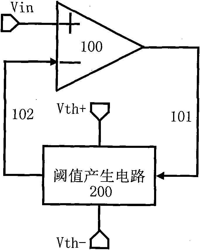
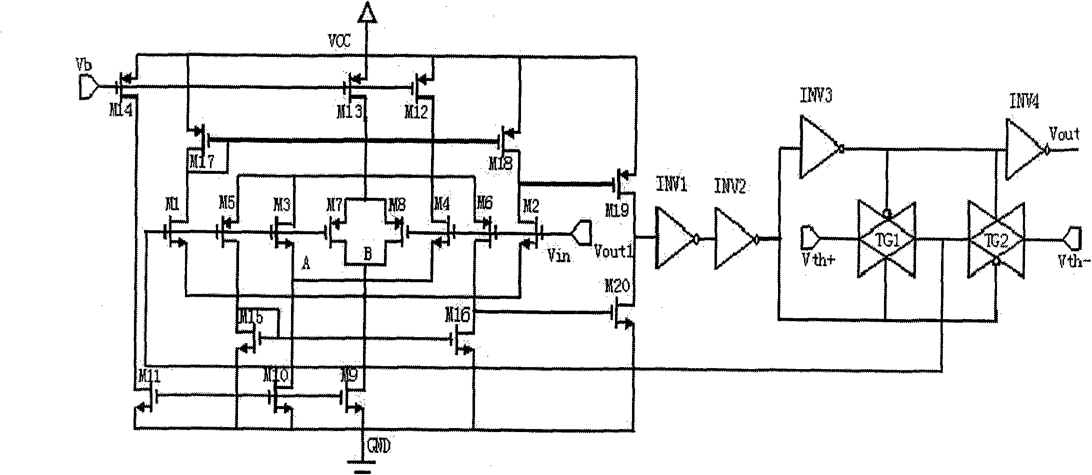
[0022] The comparator can be divided into two parts, the amplifier and the threshold generation circuit. figure 1 is the structural block diagram of the comparator, wherein 100 is the amplifier circuit, and Vin is the input terminal of the amplifier. The amplifier is output to the threshold generating circuit 200 via 101 for controlling the threshold generating circuit. Vth+ and Vth- are threshold input terminals, and the threshold voltage generated by the threshold generating circuit 200 according to selection is transmitted to the amplifier 100 via 102 for comparison. Circuit structure such as figure 2 As shown, the signal is input from Vin, compared with the comparator, and output from Vout1. Through the level of Vout1, the function of controlling the transmission gate TG1 and TG2 is realized, so that Vth+ or Vth- is output to the gate of M1 through the transmission gate. Pole is compared with Vin and output from Vout.
[0023] The specific working principle of the circ...
PUM
 Abstract
Description
Claims
Application Information
 - R&D
- Intellectual Property
- Life Sciences
- Materials
- Tech Scout
- Unparalleled Data Quality
- Higher Quality Content
- 60% Fewer Hallucinations
Browse by: Latest US Patents, China's latest patents, Technical Efficacy Thesaurus, Application Domain, Technology Topic, Popular Technical Reports.
© 2025 PatSnap. All rights reserved.Legal|Privacy policy|Modern Slavery Act Transparency Statement|Sitemap|About US| Contact US: help@patsnap.com


