Single-side welding equipment

A single-sided welding and welding line technology, applied in the direction of auxiliary equipment, welding equipment, auxiliary welding equipment, etc., can solve problems such as shaking and adverse effects of welding parts, and achieve the effect of stable welding

Active Publication Date: 2011-06-01
KOBE STEEL LTD
View PDF4 Cites 2 Cited by
  • Summary
  • Abstract
  • Description
  • Claims
  • Application Information

AI Technical Summary

Problems solved by technology

[0006] However, the welding trolley running on the rails installed on the beams of the above-mentioned length is affected by the bending of the beam due to its own weight, and shakes during running. Precisely controlled welds have adverse effects

Method used


Image

  • Single-side welding equipment
  • Single-side welding equipment
  • Single-side welding equipment

Examples


Embodiment Construction

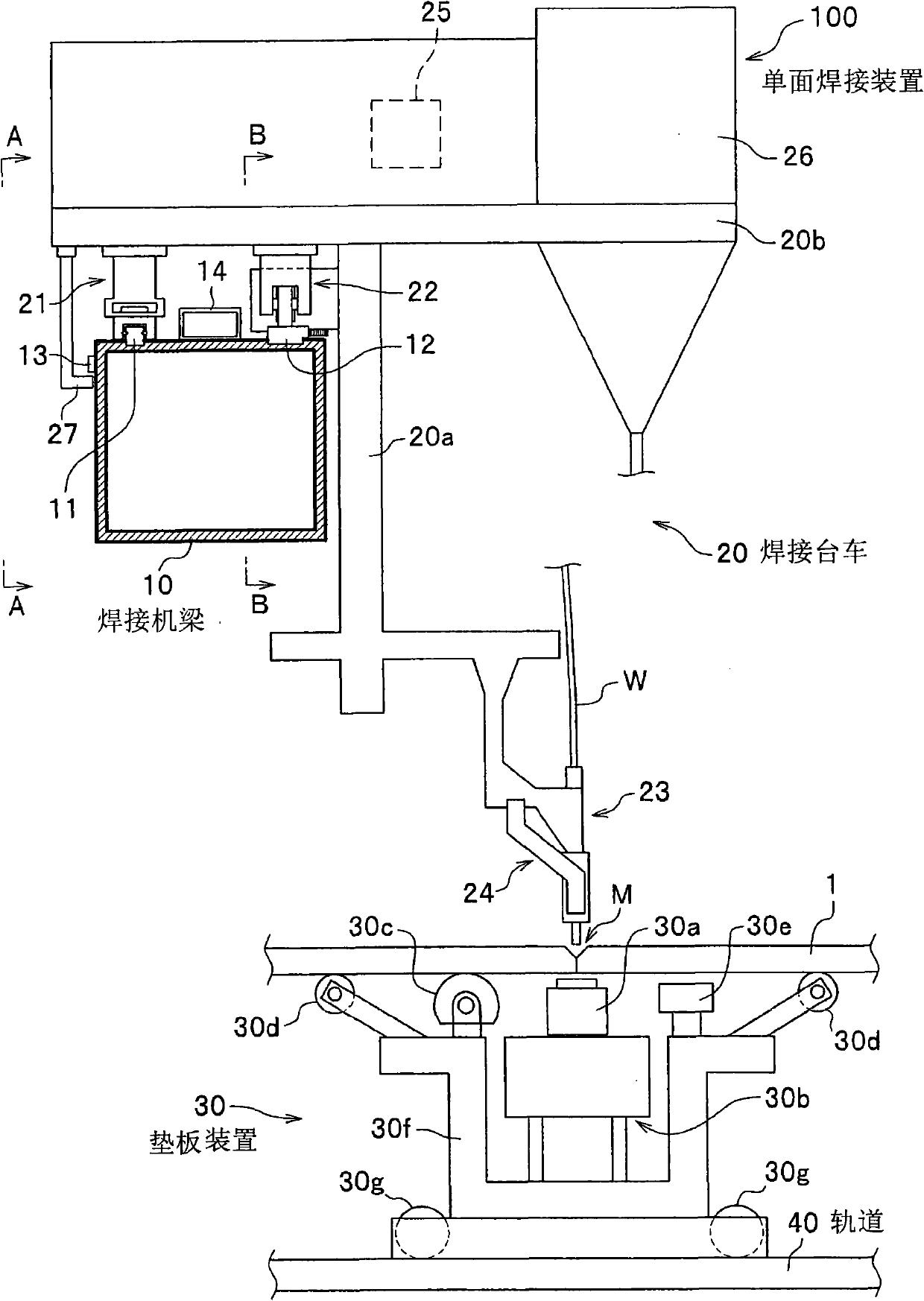
[0030] Next, the single-side welding device 100 according to the embodiment will be described with reference to the drawings.

[0031] like figure 1 As shown, the single-sided welding device 100 mainly includes a welding machine beam 10 , a welding trolley 20 suspended and supported in a cantilever state along the side surface of the welding machine beam 10 , and a backing plate device 30 arranged on the back side of the flux line M.

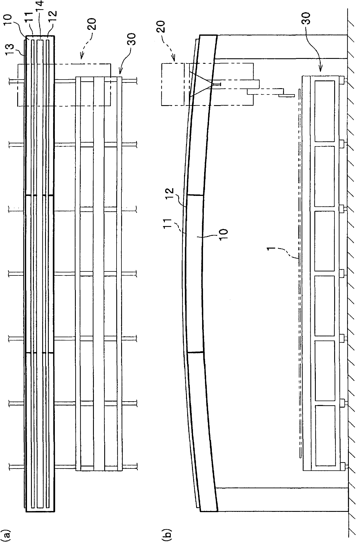
[0032] like figure 1 , image 3 As shown in (a), the welding machine beam 10 is a linearly formed frame for supporting the welding trolley 20 in a traveling manner. The welding beam 10 is formed in a hollow square pipe shape, and is made of, for example, a metal material. In addition, the welding machine 10 is substantially parallel to the welding line M for aligning the member to be welded 1 , and is formed in an elongated shape longer than the member to be welded 1 by joining a plurality of beam pieces.

[0033] like figure 1 , image 3 ...


PUM


Abstract

The invention provides a single-side welding equipment, which comprises a linear-arranged welding machine beam, a welding trolley and a backing plate device arranged at the back side of the welding line of welding assemblies. The welding trolley suspended to be supported along the side face of the welding machine beam in a cantilever state can run along the length direction of the welding machine beam.The upper surface of the welding machine beam is equipped with a bearing track, rack and pinion extending in parallel to one another along the length direction of the welding machine beam.The welding trolley comprises a first and a second running mechanisms respectively clamped with the bearing track, the rack and the pinion, a welding wire supply nozzle, a welding line position detection mechanism and a nozzle movement control mechanism.According to the above structure, the stable welding of the welding trolley running on the welding machine frame can be performed.

Description

technical field [0001] The invention relates to a single-side welding device used for single-side welding of parts to be welded such as metal plates. Background technique [0002] Conventionally, as a single-side welding device used for one-side welding of members to be welded such as metal plates, for example, a device having a configuration described in Japanese Patent No. 3526152 is known. This single-side welding device is provided with: a pair of clamping beams 4a, 4b clamping the steel plate 1 to be welded from above the steel plate 1 to be welded, and a running rail 16 arranged on the upper surface of any one of the clamping beams 4a, 4b, The rail trolley 5 on which the welding unit 16 is placed travels on the travel rail 16 to perform welding. [0003] The single-side welding device includes a first clamping beam 4a and a second clamping beam 4b that can be moved up and down, and a welding unit 6 disposed on one of the first clamping beam 4a or the second clamping b...

Claims


Application Information

Patent Timeline
Patent Type & Authority Applications(China)
IPC IPC(8): B23K37/02
Inventor 大久保宣正中尾哲也木幡茂
Owner KOBE STEEL LTD
Why Eureka
Try Eureka