Forced discharge mechanism and safety switch device for storage battery

A technology of forced discharge and safety switch, which is applied in battery circuit devices, secondary battery charging/discharging, electric switches, etc., can solve problems such as heat generation and lack of safety, and achieve the effect of suppressing heat generation

Inactive Publication Date: 2011-06-01
SHARP KK
View PDF7 Cites 7 Cited by
  • Summary
  • Abstract
  • Description
  • Claims
  • Application Information

AI Technical Summary

Problems solved by technology

[0018] In addition, in the secondary battery described in Patent Document 2, the battery can be discharged by forcibly conducting between the pair of power transmission paths connecting the positive electrode and the negative electrode of the battery, but Discharge the battery after the positive and negative electrodes are wetted with water, etc.
In this regard, although the discharge is carried out, the heat-shrinkable tube must wait until it reaches a predetermined temperature or higher and shrinks. Incurrence of adverse conditions such as heat generation, loss of safety when abnormal conditions such as water soaking occur

Method used


Image

  • Forced discharge mechanism and safety switch device for storage battery
  • Forced discharge mechanism and safety switch device for storage battery
  • Forced discharge mechanism and safety switch device for storage battery

Examples


no. 1 approach

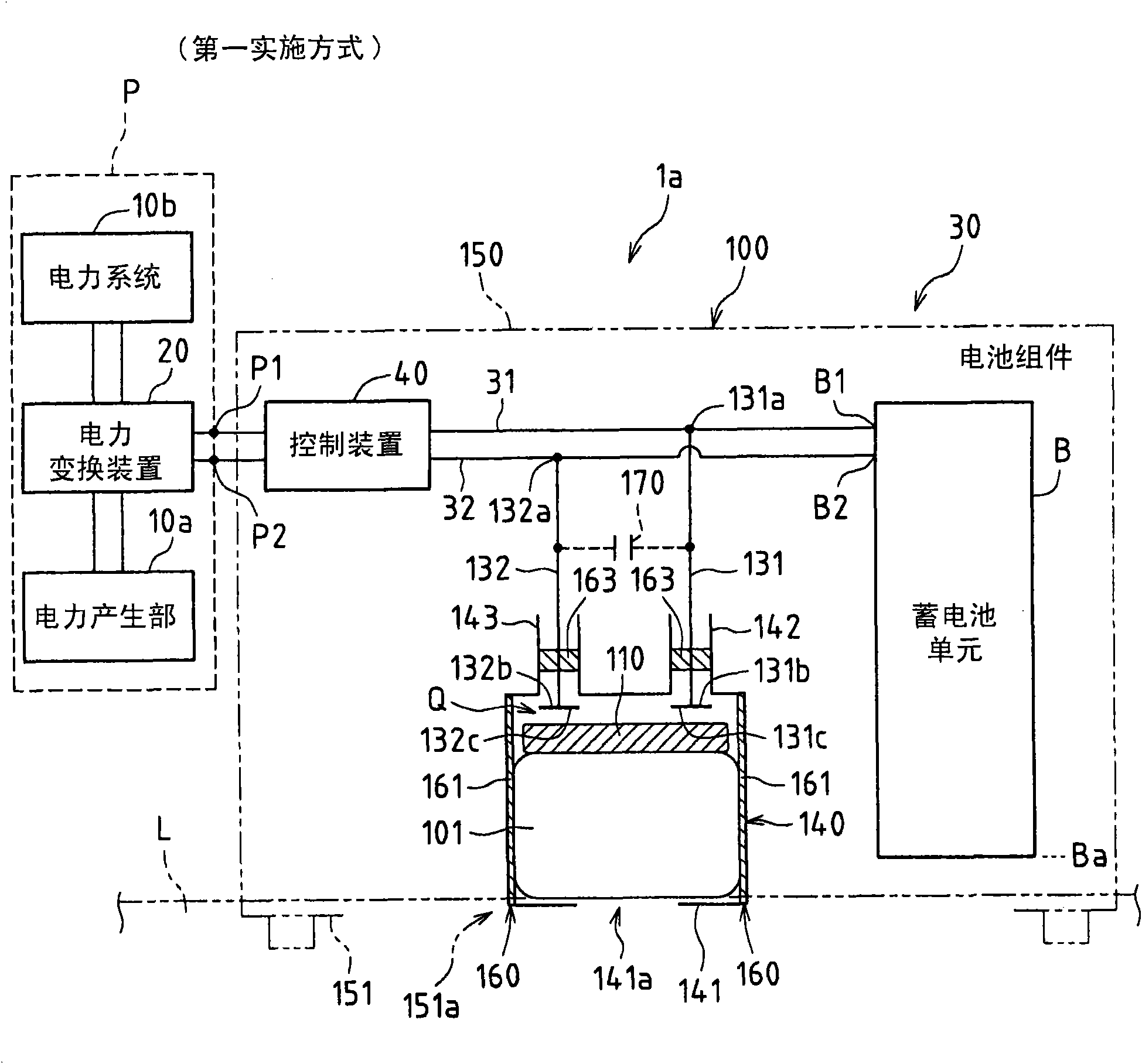
[0134] figure 1 It is a figure which shows an example which applied the forced discharge mechanism 100 of the storage battery B of 1st Embodiment of this invention to the power generation system 1a.

[0135] figure 1 In the power generation system 1a shown, a power conversion device 20 (here, an inverter) converts DC power from a power generation unit 10a into AC power, supplies the converted AC power to a power system 10b, and communicates with The power system 10b is a system that performs system cooperation. The power generation system 1a supplies the battery B with DC power from the power generation unit 10a. Furthermore, the power generation unit 10a, the power system 10b, and the power conversion device 20 function as an external power source P. As shown in FIG.

[0136] The power generator 10a may be an electric device such as a solar cell that directly converts natural energy such as sunlight into electric power, or may be an electric device such as a fuel cell th...

no. 2 approach

[0187] Figure 5 It is a schematic diagram which shows an example of applying the safety switch apparatus 200a of 2nd Embodiment of this invention to the power generation system 1b.

[0188] Figure 5 The power generation system shown in 1b, is at figure 1 The illustrated power generation system 1a includes a system of safety switchgear 200a.

[0189] exist Figure 5 In the power generation system 1b of the second embodiment shown, for the figure 1 The same constituent elements of the power generation system 1a of the first embodiment shown are given the same reference numerals, and description thereof will be omitted. In this case, even for the following Figure 7 to Figure 11 The same applies to the third to seventh embodiments shown.

[0190] The safety switch device 200a includes a disconnecting device 210a, which is able to connect the conduction portions (the branch points between the discharge passages 131 and 132) 31a, 32a and The external power sources P are ...

no. 3 approach

[0205] Figure 7 It is a figure which shows an example which applied the safety switch apparatus 200b of 3rd Embodiment of this invention to the power generation system 1c.

[0206] Figure 7 The power generation system 1c shown is in Figure 5 In the power generation system 1b shown, a disconnection device 210b is provided instead of the disconnection device 210a. The disconnection device 210b is a device in which the energization detection sensor 50b is provided instead of the water detection sensor 50a in the disconnection device 210a.

[0207] The energization detection sensor 50 b is connected in series to at least one of the discharge paths 131 , 132 (here, the discharge path 132 ), and is connected to an input system of the control device 40 . The energization detection sensor 50b is set as a current detector here.

[0208] According to the safety switch device 200b of the third embodiment, in the forced discharge mechanism 100, the floating part 101 floats up and t...


PUM


Abstract

The invention provides a forced discharge mechanism and a safety switch device for a storage battery. The forced discharge mechanism for the storage battery for forcibly establishing conduction between a pair of power transport paths that are respectively connected to a positive electrode terminal and a negative electrode terminal of the storage battery includes an electric resistor for establishing conduction between the power transport paths, and the electric resistor is movable due to a buoyant force of liquid that has entered.

Description

[0001] This application claims priority based on Patent Application No. 2009-272252 filed in Japan on November 30, 2009. By mentioning here, the entire contents of which are incorporated into this application. technical field [0002] The present invention relates to a forced discharge mechanism and a safety switch device for a storage battery, for example, to a forced discharge mechanism and a safety switch device for a storage battery included in a battery pack having a protective function. Background technique [0003] Conventional storage batteries (secondary batteries) include, for example, battery packs that have a protection function that operates when an abnormal state occurs. [0004] As a battery pack having this protection function, a battery pack having a protection function that operates when an abnormal state such as water soaking occurs will be described below as an example. [0005] For example, batteries of battery packs used outdoors are used to back up th...

Claims


Application Information

Patent Timeline
Patent Type & Authority Applications(China)
IPC IPC(8): H01M2/34H01M2/20H02J7/00H01H9/54H01H35/18H01M8/00H01M10/42H01M10/44H01M10/60H01M10/613H01M10/625H01M10/627H01M50/574H02H5/00H02H7/18
CPCH01M10/44H01M10/465H01M2/34H02J7/0031H01M10/48Y02E60/12Y02E60/10H01M50/574H02H7/18H02H5/04
Inventor 米田哲也
Owner SHARP KK
Why Eureka
Try Eureka