Motor control circuit, control method thereof and electronic device with imaging function

A technology for controlling circuits and motors, applied in motor control, AC motor control, single motor speed/torque control, etc., can solve problems such as noise system instability, and achieve the effect of accurate positioning

Inactive Publication Date: 2015-03-18
ROHM CO LTD
View PDF10 Cites 0 Cited by
  • Summary
  • Abstract
  • Description
  • Claims
  • Application Information

AI Technical Summary

Problems solved by technology

However, this method has a problem that noise occurs or the system becomes unstable due to widening the frequency band
Such problems are not limited to the above-mentioned shake correction mechanism, and may occur in various actuators (motors).

Method used


Image

  • Motor control circuit, control method thereof and electronic device with imaging function
  • Motor control circuit, control method thereof and electronic device with imaging function
  • Motor control circuit, control method thereof and electronic device with imaging function

Examples


Embodiment Construction

[0026] Hereinafter, the present invention will be described based on preferred embodiments with reference to the drawings. The same or equivalent structural elements, parts, and processes shown in the respective drawings are given the same reference numerals, and repeated descriptions are appropriately omitted. In addition, the embodiment is only an illustration and does not limit the invention, and all the features and their combinations described in the embodiment are not essential to the invention.

[0027] In this specification, "the connected state of component A and component B", in addition to the case where component A and component B are directly connected by physical means, also includes other components that do not affect the electrical connection state between component A and component B. And the case of indirect connection.

[0028] Similarly, "the state in which the component C is disposed between the component A and the component B", in addition to the case where th...


PUM


Abstract

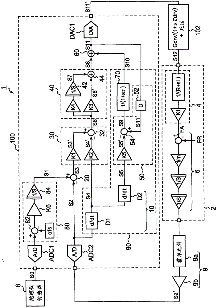
A control circuit generates a driving signal indicating an actuator torque. A first operation unit generates position, speed, and acceleration signals, based upon a detection signal indicating the actuator mover state. A second operation unit generates a first difference signal indicating the difference between a target signal and the position signal. A third operation unit generates a second difference signal indicating the difference between signals based on the first difference signal and the speed signal. A fourth operation unit generates a position control signal such that the second difference signal becomes zero. A fifth operation unit generates a third difference signal indicating the difference between signals based on a driving signal and the acceleration signal. A sixth operation unit generates a driving signal by summing a signal based on the position control signal and a disturbance estimation signal based on the third difference signal.

Description

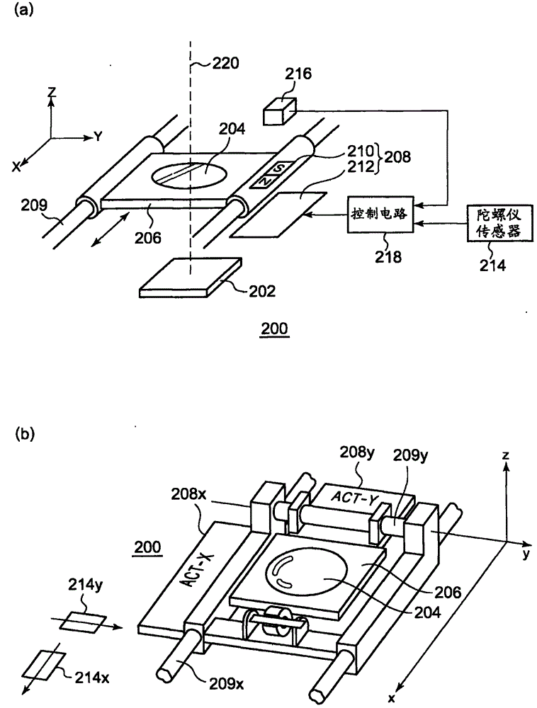
Technical field [0001] The present invention relates to the driving technology of electric motors. Background technique [0002] Digital cameras, digital video cameras, and camera-attached mobile phone terminals, such as electronic devices with shooting functions, are equipped with a shake correction function. figure 1 (a) and (b) are diagrams showing the structure of an imaging device having a shake correction mechanism. Reference figure 1 (a) The photographing device 200 includes: a photographing sensor 202, a lens 204, a lens holder 206, an actuator (motor) 208, a gyro sensor (gyro sensor) 214, a Hall element 216, and a motor control circuit 218 . [0003] The lens 204 for shake correction is located on the optical axis 220. The lens holder 206 for holding the lens 204 is axially supported by a shaft 209 and can move in the X-axis direction. figure 1 (b) is a perspective view of the shake correction mechanism. versus figure 1 The movable mechanism with the same X-axis directi...

Claims


Application Information

Patent Timeline
Patent Type & Authority Patents(China)
IPC IPC(8): H02P6/08G03B5/00H02P29/00
CPCH02P23/005G03B2205/0007G03B5/02H02P23/18
Inventor 清水立郎
Owner ROHM CO LTD
Why Eureka
Try Eureka