Heat radiating device

一种散热装置、散热片的技术,应用在间接换热器、照明和加热设备、冷却/通风/加热改造等方向,能够解决不利热管散热、影响散热装置散热效果等问题,达到增强热交换、提升散热效果的效果

Inactive Publication Date: 2011-06-01
HONG FU JIN PRECISION IND (SHENZHEN) CO LTD +1
View PDF7 Cites 4 Cited by
  • Summary
  • Abstract
  • Description
  • Claims
  • Application Information

AI Technical Summary

Problems solved by technology

However, due to the certain thermal resistance of the heat dissipation fins, the temperature of the heat dissipation fins around the heat pipe is relatively high, and when the airflow generated by the fan flows through the heat pipe, due to the blocking of the heat pipe, an air heat is formed behind the heat pipe. The swivel socket is not conducive to the heat dissipation of the heat pipe and affects the heat dissipation effect of the heat sink

Method used


Image

  • Heat radiating device
  • Heat radiating device
  • Heat radiating device

Examples


Embodiment Construction

[0013] The heat dissipation device of the present invention will be further described below with reference to the accompanying drawings.

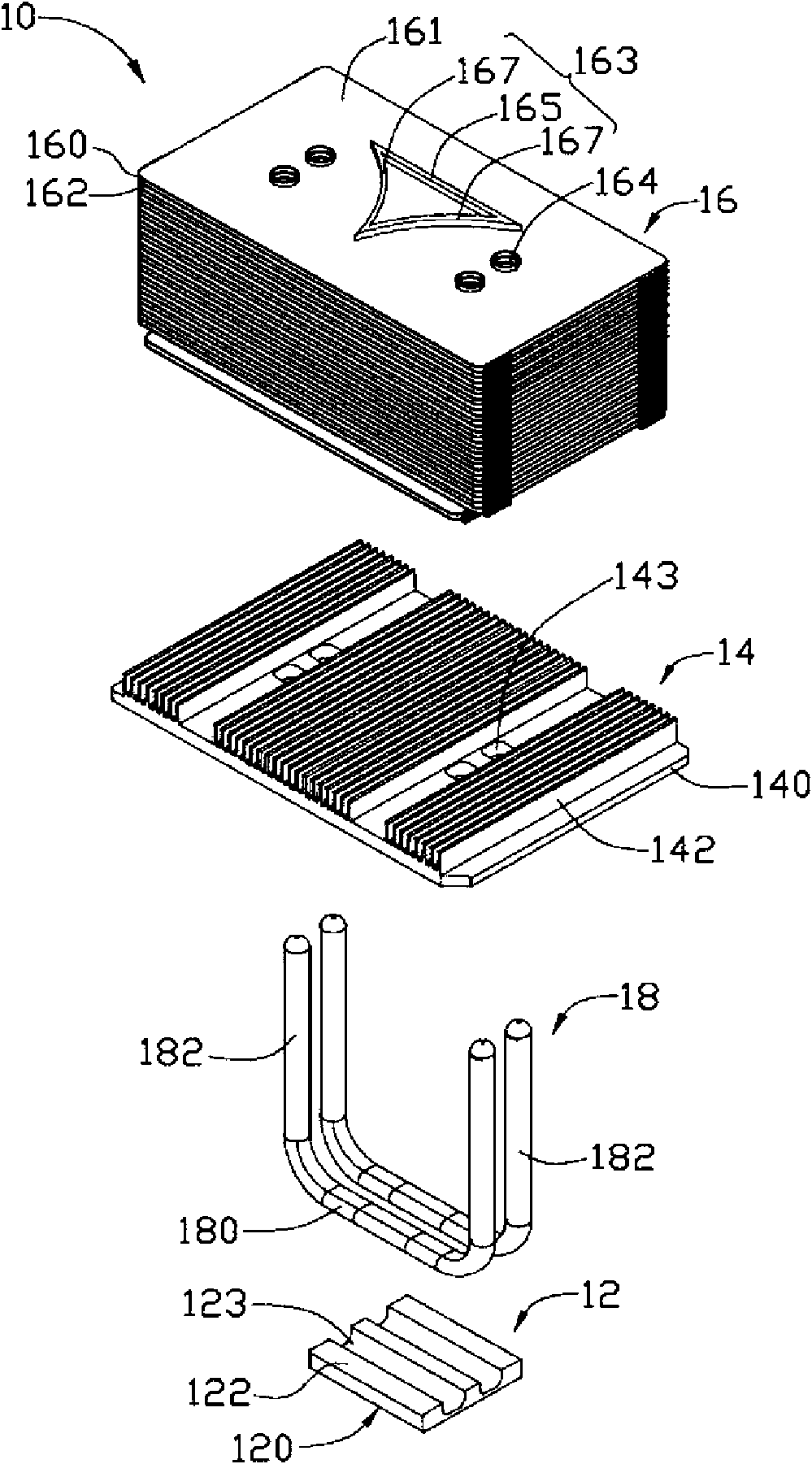
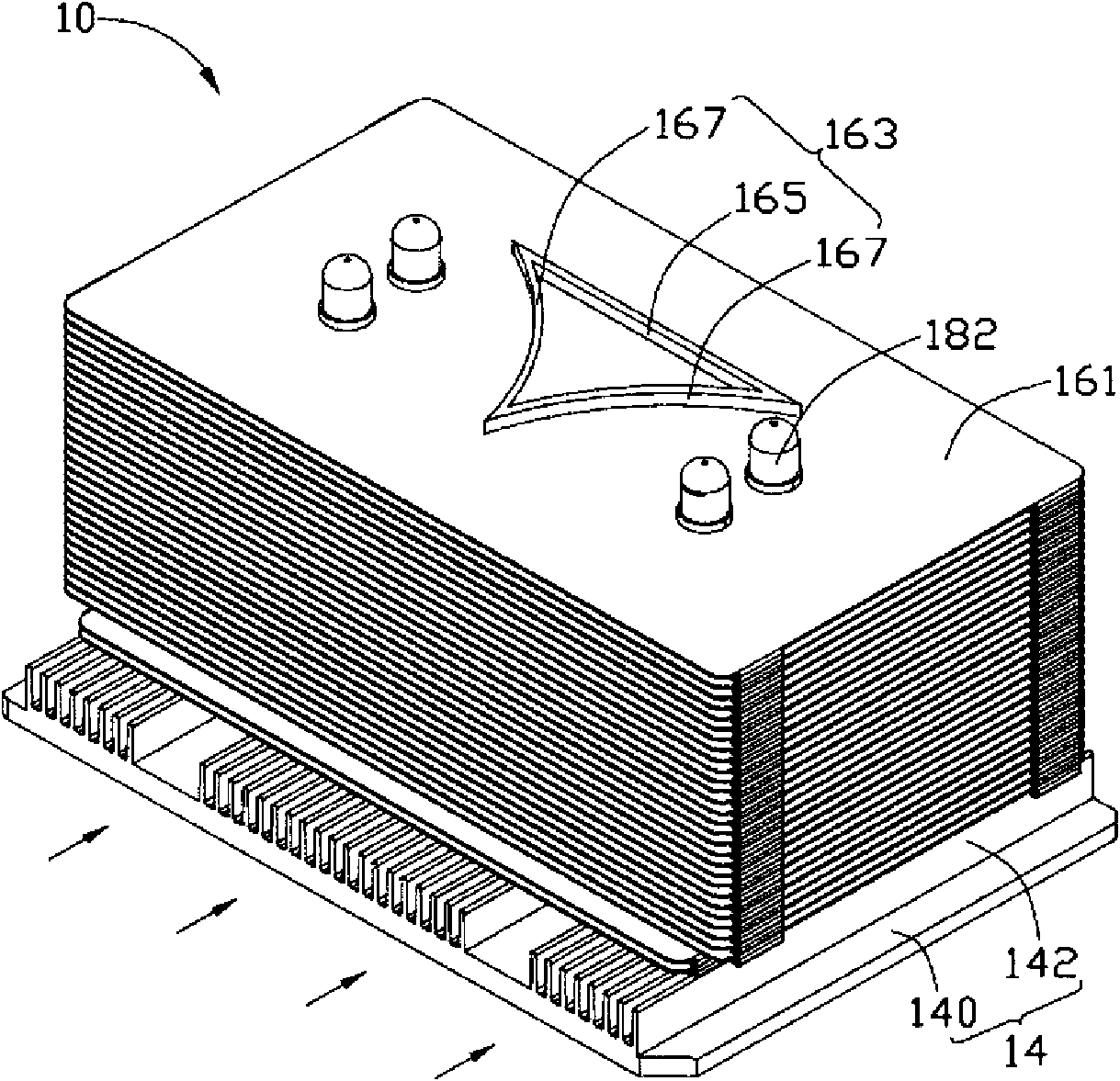
[0014] Such as figure 1 and figure 2 As shown, the heat dissipation device 10 includes a base plate 12, a first heat sink 14 disposed on the base plate 12, a second heat sink 16 disposed on the first heat sink 14, and a second heat sink 16 disposed on the base plate 12 and the base plate 12. Two heat pipes 18 between the first radiator 14 and the second radiator 16 .

[0015] The substrate 12 is in the shape of a rectangular plate and has a flat lower surface 120 and an upper surface 122 opposite to the lower surface 120 . Two parallel horizontal and vertical grooves 123 are arranged side by side on the upper surface 122 .

[0016] The first heat sink 14 is attached on the upper surface 122 of the substrate 12 , and includes a bottom plate 140 and a plurality of first heat sink fins 142 vertically extending upward from the top surface o...


PUM


Abstract

The invention discloses a heat radiating device comprising a heat radiator and at least one heat pipe penetrated in the heat radiator; the heat radiator comprises a plurality of heat radiating fins arranged at intervals; air flow channels for air flow to pass through are arranged between every two adjacent heat radiating fans; each heat radiating fin is provided with a perforation for the heat pipe to penetrate in; a flow guiding structure is arranged on a position of each heat radiating fin, near the perforation; the flow guiding structure comprises an arc-shaped wall arranged around one side of the perforation; the arc-shaped wall is obliquely arranged opposite to the direction of the air flow in the air flow channel to guide the air flow in the air flow channel to the heat pipe, thereby enhancing the heat exchange of the heat pipe, weakening the influence of a heat spin in the rear of the heat pipe on heat radiation and further improving the heat radiating effect o the heat radiating device.

Description

technical field [0001] The invention relates to a heat dissipation device, in particular to a heat dissipation device for dissipating heat from electronic components. Background technique [0002] With the rapid development of the electronic information industry, the high-speed, high-frequency and integration of heat-generating electronic components such as central processing units will cause a sharp increase in heat generation. If the heat is not removed in time, the temperature of the heat-generating electronic components will rise, which will lead Damage to heat-generating electronic components or degradation of their performance. Therefore, it is necessary to dissipate heat from the heat-generating electronic components. At present, the heat dissipation method commonly used by the industry is to install a heat dissipation device on the surface of the heat-generating electronic component. [0003] Existing cooling devices generally include a radiator, a fan mounted on t...

Claims


Application Information

Patent Timeline
Patent Type & Authority Applications(China)
IPC IPC(8): H05K7/20H01L23/34H01L23/367
CPCH01L23/427H01L23/467H01L2924/0002F28D15/0275H01L2924/00
Inventor 马小峰叶振兴
Owner HONG FU JIN PRECISION IND (SHENZHEN) CO LTD
Why Eureka
Try Eureka