Motor vehicle and body floor structure thereof

A technology for underbody and automobiles, applied in the automotive field, can solve problems such as increased vehicle weight, and achieve the effects of reducing the total vehicle weight, improving safety, and eliminating reinforcement elements and materials.

Inactive Publication Date: 2011-06-08
GM GLOBAL TECH OPERATIONS LLC
View PDF4 Cites 9 Cited by
  • Summary
  • Abstract
  • Description
  • Claims
  • Application Information

AI Technical Summary

Problems solved by technology

This requires stiffening elements arranged in the body which in turn lead to an increase in the weight of the entire vehicle

Method used


Image

  • Motor vehicle and body floor structure thereof
  • Motor vehicle and body floor structure thereof
  • Motor vehicle and body floor structure thereof

Examples


Embodiment Construction

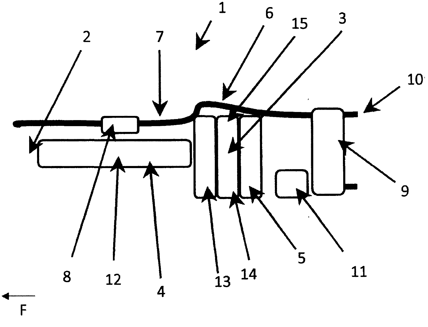
[0034] figure 1 A schematic plan view of a motor vehicle underbody structure 1 is shown according to a first embodiment of the invention, in which energy storage devices 4 , 5 are arranged for storing energy for driving the vehicle.

[0035] The underbody structure 1 here comprises the passenger compartment, wherein in the longitudinal center there is a central tunnel 2 extending between the engine compartment and the rear axle, and a central tunnel 2 opposite to the direction of travel F connected to the underbody structure 1 . rear seat area 3. Here, a first receiving recess (not shown) is provided inside the center tank 2 , in which a first energy storage device 4 for storing energy for driving the vehicle is arranged. The rear seat area 3 of the underbody structure 1 has a second receiving recess (not shown), in which a second energy storage device 5 for storing energy for driving the vehicle is arranged.

[0036] Furthermore, an exhaust system 6 is shown which is arrang...


PUM


Abstract

The present invention relates to a body floor structure (1, 21, 31, 41), which, within the center tunnel (2), comprises a first receiving clearance for receiving a first energy storage device (4, 34, 44) for the storage of energy for driving the vehicle and in the rear seat region (3) comprises a second receiving clearance for receiving a second energy storage device (5, 25) for the storage of energy for driving the vehicle and a motor vehicle, specifically a hybrid vehicle, which comprises this body floor structure (1, 21, 31, 41).

Description

technical field [0001] The invention relates to a motor vehicle, in particular to an arrangement of an energy storage device for storing energy for driving the vehicle, and to an underbody structure for a motor vehicle. A motor vehicle here is in particular a hybrid vehicle. Background technique [0002] A series of requirements are placed on the arrangement of the energy store, especially in passenger cars. The requirements in terms of safety technology take the lead. The fuel tank should therefore be arranged as rationally and stably as possible in the vehicle body with regard to the hazards of leaking fluid. However, the requirements regarding the usable space in the passenger compartment and the luggage compartment as well as environmental protection and the overall vehicle weight also play an important role here. [0003] In most known motor vehicles, the fuel tank is arranged in the underbody structure in the region of the rear seats. With this arrangement, the mou...

Claims


Application Information

Patent Timeline
Patent Type & Authority Applications(China)
IPC IPC(8): B62D25/20B60K15/063B60K1/04
CPCB60K2001/0438B62D25/2009B60K15/063B60K1/04B60K2001/0433B60K15/03B62D25/20B60K6/12
Inventor 斯坦尼斯劳·克利梅克于尔根·赫尔伯特
Owner GM GLOBAL TECH OPERATIONS LLC
Why Eureka
Try Eureka