Small temperature-rise low-entropy mixing combustion engine

An engine, piston engine technology, used in combustion engines, internal combustion piston engines, engine components, etc.

Inactive Publication Date: 2011-06-08
靳北彪
View PDF6 Cites 34 Cited by
  • Summary
  • Abstract
  • Description
  • Claims
  • Application Information

AI Technical Summary

Problems solved by technology

However, there is no plan to specify the amount of expansion agent injected into the combustion chamber and the pressure state in the combustion chamber before injection. However, the amount of expansion agent injected into the combustion chamber and the pressure an

Method used


Image

  • Small temperature-rise low-entropy mixing combustion engine
  • Small temperature-rise low-entropy mixing combustion engine
  • Small temperature-rise low-entropy mixing combustion engine

Examples


Embodiment 1

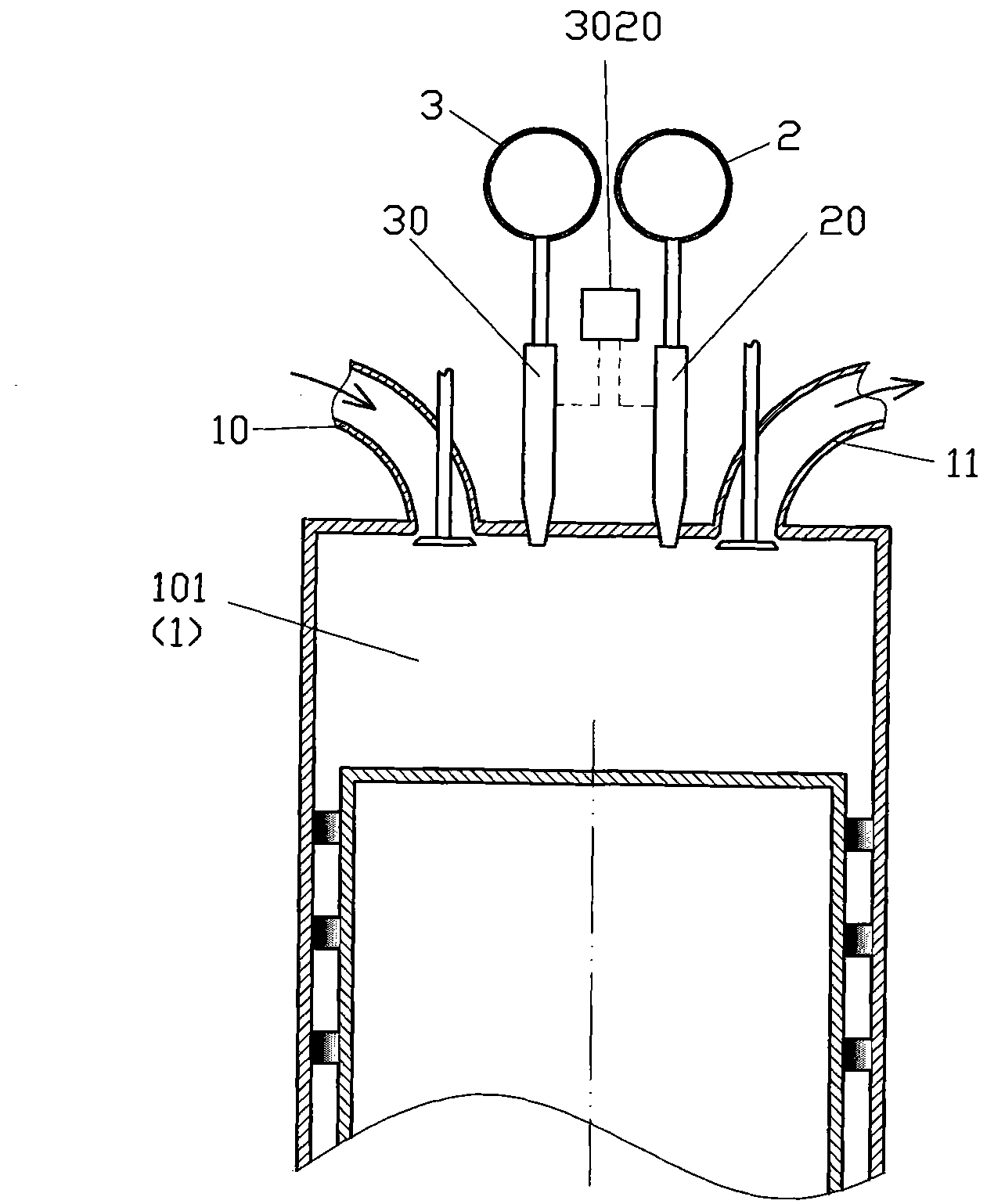
[0068] like figure 1 The shown small temperature rise and low entropy mixed combustion engine includes a combustion chamber 1, an expander source 2 and a fuel source 3, and the combustion chamber 1 is set as a piston engine combustion chamber 101 or as a turbine combustion chamber 102, and the fuel The source 3 communicates with the combustion chamber 1 through the fuel introduction control mechanism 30, the expansion agent source 2 communicates with the combustion chamber 1 through the expansion agent introduction control mechanism 20, and the fuel introduction control mechanism 30 and the expansion agent introduction The control mechanism 20 is controlled by the combustion control device 3020 to realize that more than 5% of the heat generated by the combustion of the fuel entering the combustion chamber 1 in the fuel source 3 has been introduced into the combustion chamber 1 in the combustion chamber 1 The expansion agent in the expansion agent source 2 absorbs; in the stru...

Embodiment 2

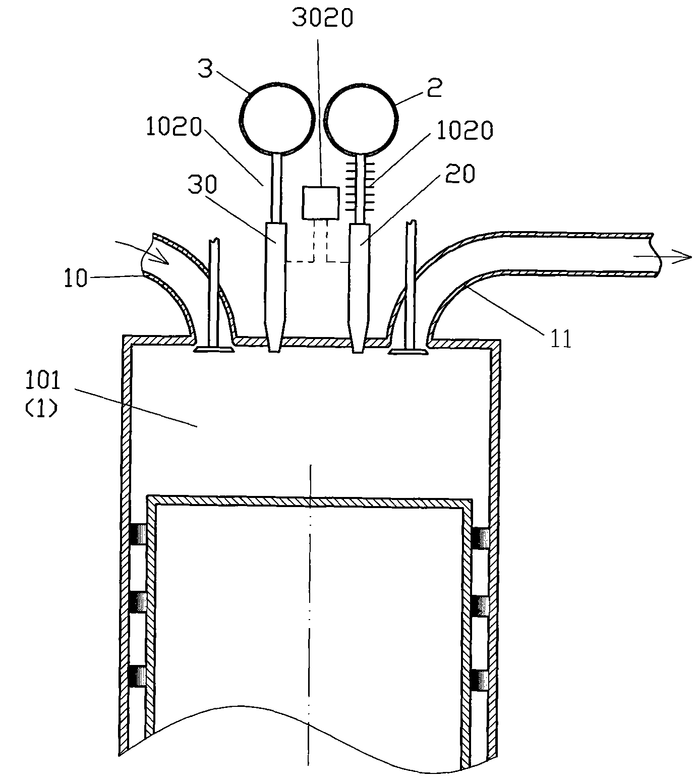
[0074] like figure 2 The difference between the small temperature-rise and low-entropy co-combustion engine shown in Embodiment 1 is that an expander heat absorbing heat exchanger 1020 is set between the combustion chamber 1 and the expander source 2 to make the expander The expansion agent in the agent source 2 absorbs heat in the expansion agent heat absorption heat exchanger 1020, and the combustion chamber 1 is set as an adiabatic combustion chamber.

Embodiment 3

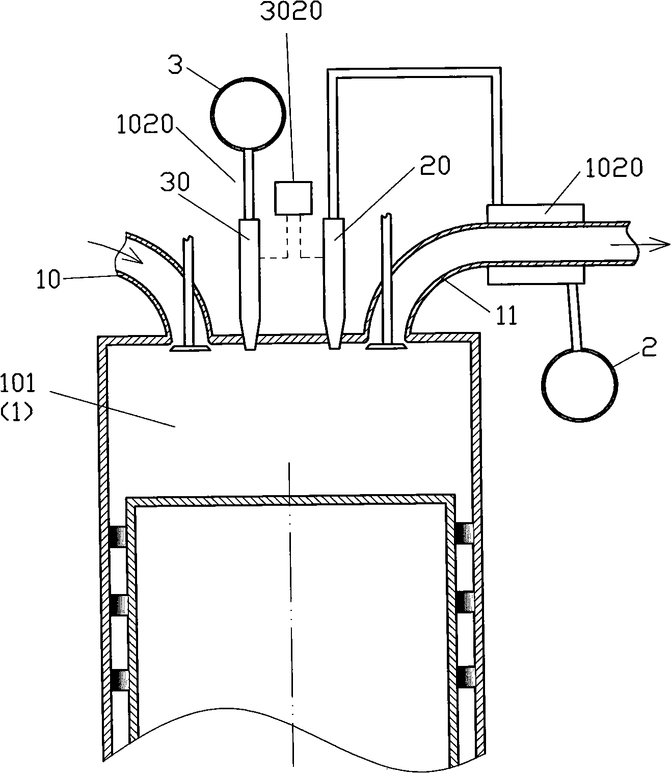
[0076] like image 3 The difference between the low-temperature-rise low-entropy co-combustion engine shown and Embodiment 1 is that the heat source of the expander heat absorption heat exchanger 1020 is set as the waste heat of the low-temperature-rise low-entropy co-combustion engine. The expansion agent in the expansion agent source 2 enters the combustion chamber 1 after absorbing heat in the expansion agent heat absorption heat exchanger 1020 to reach a critical state, a supercritical state or an ultra-supercritical state. The fuel in the fuel source 3 is set as ethanol, the expander in the expander source 2 is set as water, and the fuel source 3 and the expander source 2 are set as the same aqueous ethanol storage tank.


PUM


Abstract

The invention discloses a small temperature-rise low-entropy mixing combustion engine which comprises a combustion chamber, an expanding agent source and a fuel source, wherein the combustion chamber is arranged as a piston engine combustion chamber and a marine engine combustion chamber; the fuel source is communicated with the combustion chamber through a fuel lead-in control mechanism; the expanding agent source is communicated with the combustion chamber through an expanding agent lead-in control mechanism; and more than 5% of the heat generated by the combustion of the fuel in the fuel source entering the combustion chamber is absorbed by the expanding agent in the expanding agent source in the combustion chamber by virtue of the control of a combustion control device for the fuel lead-in control mechanism and the expanding agent lead-in control mechanism. The small temperature-rise low-entropy mixing combustion engine disclosed by the invention has the advantages of high efficiency and good environmental friendliness.

Description

technical field [0001] The invention relates to the field of thermal energy and power, in particular to a small temperature rise and low entropy mixed combustion engine. Background technique [0002] In order to improve the efficiency of traditional internal combustion engines (including piston internal combustion engines and internal combustion turbines), many proposals have been made to inject expansion agents into the combustion chambers. But there is no plan to clearly inject the amount of expansion agent into the combustion chamber and the pressure state in the combustion chamber before injection. However, the amount of injection expansion agent into the combustion chamber and the pressure and temperature state in the combustion chamber before combustion are the factors that affect the injection of expansion agent into the combustion chamber of the internal combustion engine. One of the most important factors in the efficiency of the internal combustion engine in the sc...

Claims


Application Information

Patent Timeline
IPC IPC(8): F02M25/00F02M19/12F02M15/00F02G5/00F02C3/30F02C9/18F02C9/50
CPCY02T10/14Y02T10/166Y02T10/12
Inventor 靳北彪
Owner 靳北彪
Why Eureka
Try Eureka