Solenoid arrangement and valve arrangement

A technology of magnet device and valve device, which is applied in the direction of electromagnets, magnets, electromagnets with armatures, etc., to achieve the effect of good closing time

Inactive Publication Date: 2014-07-16
ROBERT BOSCH GMBH
View PDF4 Cites 0 Cited by
  • Summary
  • Abstract
  • Description
  • Claims
  • Application Information

AI Technical Summary

Problems solved by technology

But fluid valves require sufficient operating force over a larger stroke range

Method used


Image

  • Solenoid arrangement and valve arrangement
  • Solenoid arrangement and valve arrangement
  • Solenoid arrangement and valve arrangement

Examples


Embodiment Construction

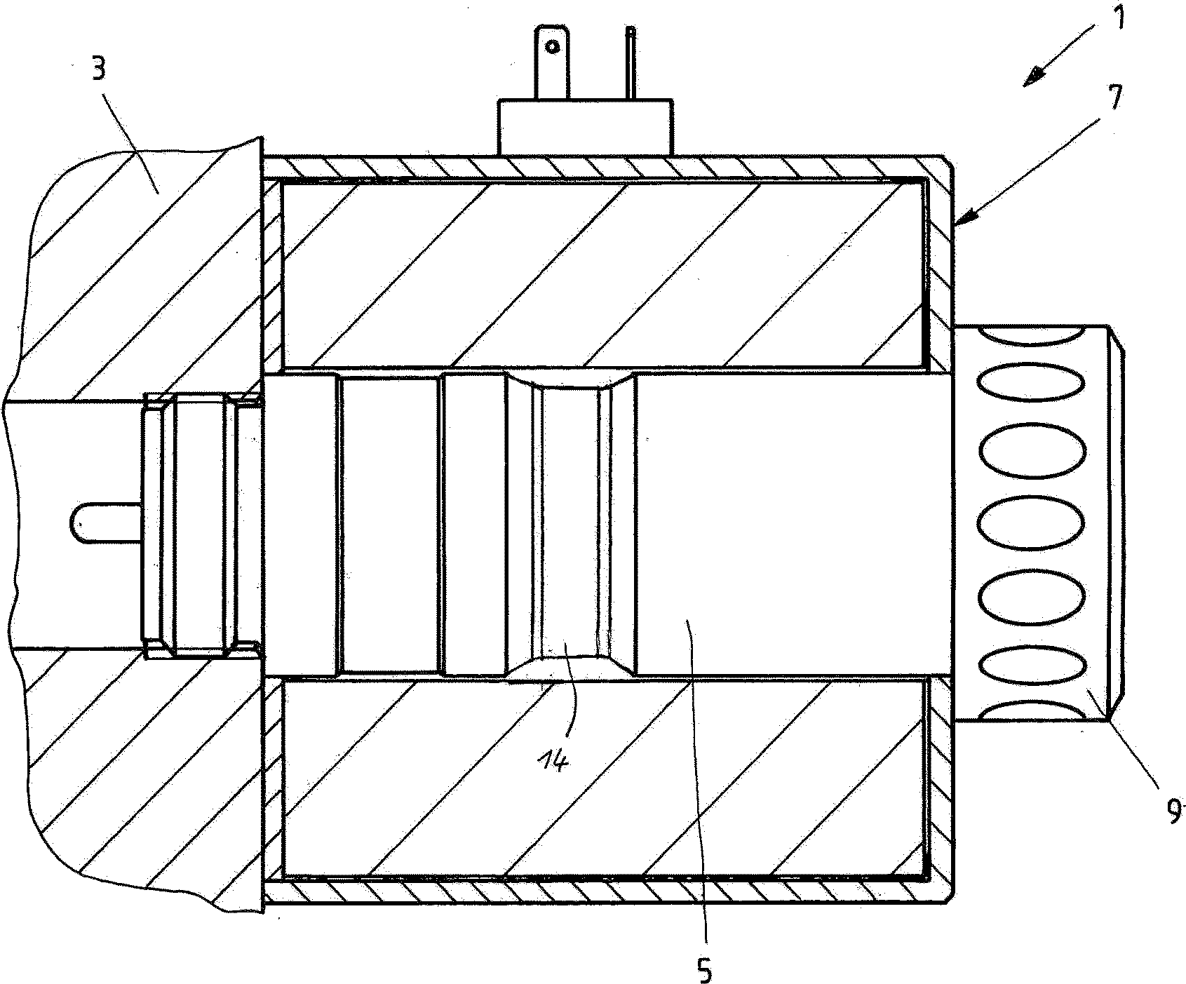
[0023] figure 1 A typical arrangement of a stroke magnet 1 is shown, as it is used for actuating fluidic switching valves. The pole tube 5 of the stroke magnet 1 is screwed into the valve bore on the valve housing 3 . An excitation coil 7 is set on the pole tube 5 . The field coil 7 is fastened to the pole tube 5 by means of nuts 9 . The pole tube 5 is constricted with respect to its outer diameter in the transition section 14 .

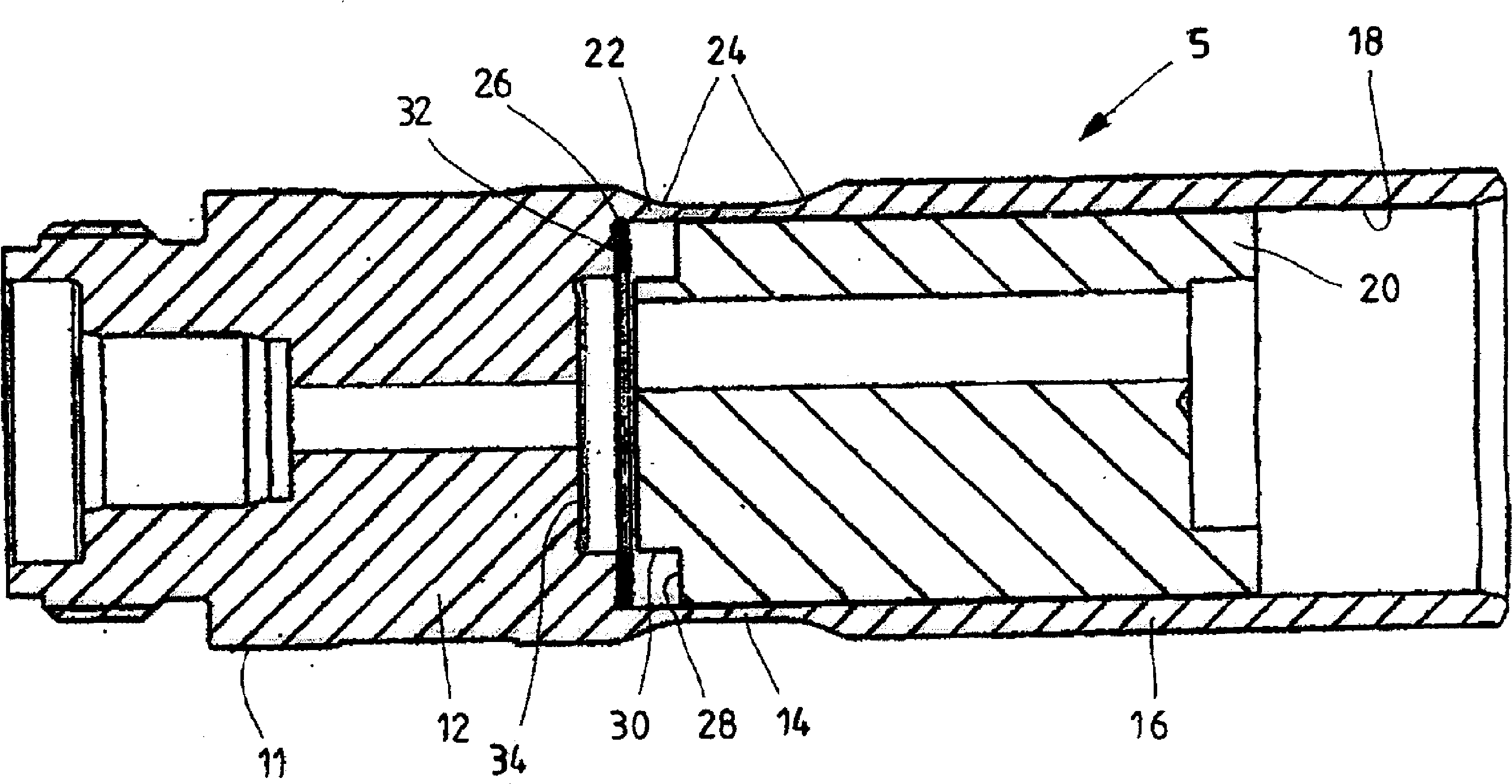
[0024] figure 2 The arrangement of the pole tube 5 according to the invention and of the armature guided in it is described. The pole tube body 11 is prepared from ferromagnetic steel, for example from a rod, by machining into the shape shown.

[0025] The pole tube body 11 is axially divided into a pole core 12 , a transition section 14 and a tube section 16 . The overall sleeve-like shape of the pole tube body 11 allows the armature 20 to be inserted into the central bore 18 . At its end facing away from the pole section 12 after the openin...


PUM


Abstract

A stroke magnet arrangement in which the magnetic discontinuity in the pole tube is formed by means of a reduction in the effective material thickness, for example a reduction in the thickness, in particular the wall thickness of the magnetically effective material, of the armature facing the pole iron The end faces of the core segments and the bases arranged on the pole core segments in the interior of the pole tube are each provided with contours which allow mutual axial overlapping. This makes it possible to obtain an advantageous influence of the force-stroke-characteristic curve of the stroke magnet with low manufacturing effort.

Description

technical field [0001] The invention relates to a stroke magnet arrangement (Hubmagnetanordung). The invention also relates to a valve arrangement. Background technique [0002] Stroke magnet arrangements of this type are frequently used in fluid technology as drives for actuating hydraulic or pneumatic valves. [0003] Fluidic actuating magnets are usually of modular construction and, in addition to the through-opening of the tappet, also have a fluid-tight pole tube in which the armature is movably guided. Put a coil body on the pole tube. The coil body is fixed with nuts. A separating ring made of non-magnetic material is usually welded between the pole core section and the tube section of the pole tube. The flux lines in the pole duct thus traverse from the pole core section to the armature. Only in this way can a working air gap be formed which is filled with force lines. [0004] It is precisely for switching valves that one uses the simplest possible constructio...

Claims


Application Information

Patent Timeline
Patent Type & Authority Patents(China)
IPC IPC(8): H01F7/13
CPCH01F7/088H01F7/081H01F7/1607H01F2007/086H01F7/13H01F2007/085
Inventor K.斯特劳斯J.格伦H.巴特尔R.舍姆普
Owner ROBERT BOSCH GMBH
Why Eureka
Try Eureka