Ladle nozzle casting combined drainage plug
A nozzle and ladle technology, applied in the field of auxiliary devices, can solve the problems of large difference in shape between the plug and the inner wall of the nozzle, inconvenient processing, storage and transportation, and the nozzle is easily covered or blocked, so as to improve the success rate of pouring and easy processing Production, easy to install, accurate and in place effect
- Summary
- Abstract
- Description
- Claims
- Application Information
AI Technical Summary
Problems solved by technology
Method used
Image
Examples
Embodiment 1
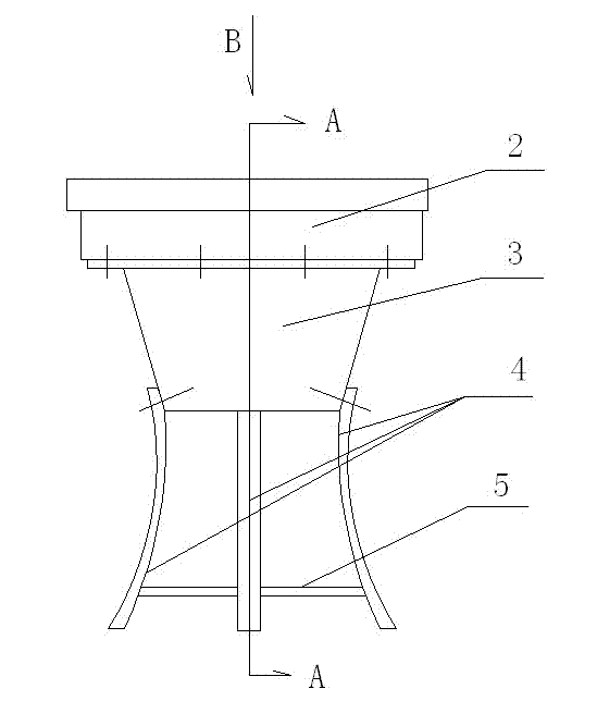
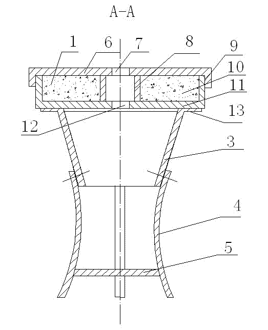
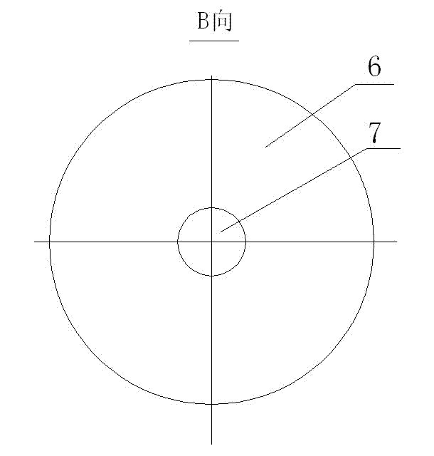
[0023] Depend on figure 1 , figure 2 , image 3 It can be seen from the figure that the ladle nozzle casting combined drainage plug is composed of a sand storage device 2, an anastomotic cylinder 3 and two pairs of clamping plates 4 connected by screws, the lower end of the clamping plates 4 is provided with a support piece 5, and the drainage sand 1 is filled in the sand storage 2 within. When in use, the drainage plug is installed on the nozzle at the bottom of the ladle, the bottom of the sand storage device is larger than the diameter of the upper part of the nozzle (not marked in the figure), and it is erected on the block around the nozzle. The tight plate 4 is pressed against the clamping plate on the opposite side by the support piece 5, and is close to the inner wall of the lower part of the nozzle.
[0024] Depend on figure 2 It can be further seen that the sand storage device is composed of a plug cover 6 and a sand storage chamber 10, both of which are made o...
Embodiment 2
[0029] Depend on Figure 4 It can be seen that the center of the plug cover 6 is provided with an upper guide hole 7, and the plug cover is provided with an upward convex annular groove 14 concentric with the upper guide hole, corresponding to the inner cylinder 8, to increase the compressive strength of the sand storage device. The wall of the outer cylinder and the side of the plug cover are provided with pin holes, and the pins are fixed to enhance the fastness of the plug cover.
Embodiment 3
[0031] Depend on Figure 5 It can be seen that the bottom plate 11 is provided with a lower concave annular groove 15 corresponding to the upper convex annular groove 14 provided by the plug cover 6, and the inner cylinder 8 is movably inserted in the upper convex annular groove of the plug cover and the bottom plate. In the concave ring groove, it is easy to make.
PUM
 Abstract
Description
Claims
Application Information
 - R&D
- Intellectual Property
- Life Sciences
- Materials
- Tech Scout
- Unparalleled Data Quality
- Higher Quality Content
- 60% Fewer Hallucinations
Browse by: Latest US Patents, China's latest patents, Technical Efficacy Thesaurus, Application Domain, Technology Topic, Popular Technical Reports.
© 2025 PatSnap. All rights reserved.Legal|Privacy policy|Modern Slavery Act Transparency Statement|Sitemap|About US| Contact US: help@patsnap.com


