Low emissivity glass

A low-emissivity glass and glass substrate technology, applied in the field of low-emission glass, can solve problems such as difficulty in ensuring consistency of film thickness, unsatisfactory low-emission effect, and long-term use of glass, and achieve good industrial application prospects and high visible light Good transmittance and heat insulation effect

Inactive Publication Date: 2011-06-15
HUAZHONG UNIV OF SCI & TECH
View PDF6 Cites 20 Cited by
  • Summary
  • Abstract
  • Description
  • Claims
  • Application Information

AI Technical Summary

Problems solved by technology

Its disadvantages are: it can only deposit sunshade film but not heat insulation film; it can only deposit non-selective absorbing layer, that is, single-layer monochromatic film layer; due to the characteristics of chemical plating itself that is not easy to be controlled, it is difficult to guarantee that each batch of film The consistency of the thickness of the layer, so there are very few buildings that use gel film glass in large areas.
For the silver layer/dielectric layer structure, although the outer dielectric layer can protect the silver layer to prevent it from being corroded and lose its anti-radiation effect; however, due to the weak bonding force between the silver layer and the glass, it can be wiped gently fall off, so the silver layer is directly adjacent to the glass, and the low-emissivity layer is easy to fall off, which affects the long-term use of the glass
For the structure of dielectric layer/silver la

Method used


Image

  • Low emissivity glass
  • Low emissivity glass
  • Low emissivity glass

Examples


Embodiment 1

[0032] (1) Use magnetron sputtering to plate each film layer separately, and determine the optimal condition of sputtering by comparing their transmission in the spectral range; then measure its thickness to calculate its optimal condition sputtering rate. The optional parameters are as follows:

[0033]

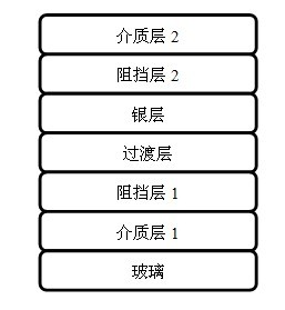
[0034](2). First, the dielectric layer 1 is plated on the transparent glass surface, the sputtering time is 5, 6, 7, and 8 minutes, and the thickness is 38.7nm, 46.44nm, 54.18nm, and 61.92nm respectively; followed by the barrier layer 1 , the sputtering time of the barrier layer 1 is NiOx——7s, CrOx——6s, the thickness is NiOx——1nm, CrOx——1nm; moreover, the sputtering time of the transition layer is 2s, and the thickness is 3.49nm Next, the metal silver layer is plated, the sputtering time of the metal silver layer is 4s, and the thickness is 13.12nm; then it is still a barrier layer 2, and its plating method and time are the same as the previous barrier layer 1; each film...

Embodiment 2

[0039] Dielectric layer 1 (ZnO) is plated on the surface of transparent glass, the sputtering time is 7 minutes, and the thickness is 54.18nm; followed by barrier layer 1, the sputtering time of barrier layer 1 is NiOx - 3.5s, CrOx - 3s , the thickness is NiOx——0.5nm, CrOx——0.5nm; Furthermore, the transition layer (Zn) is plated, the sputtering time of the transition layer (Zn) is 2s, and the thickness is 3nm; next, the metal silver layer is plated, and the metal silver layer The sputtering time is 2s, 3s, 4s, 5s, the thickness is 6.56nm, 9.84nm, 13.12nm, 16.4nm, and then it is the barrier layer 2. The plating method and time of the barrier layer 2 are the same as the previous barrier layer 1; They are plated by magnetron sputtering. In addition, each film layer is not independent, and their adjacent surfaces penetrate each other, so they have a good bonding force.

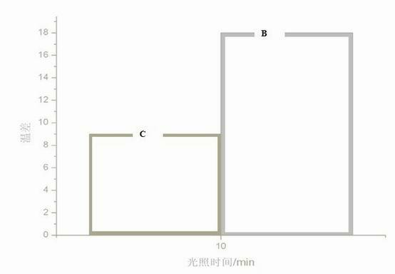
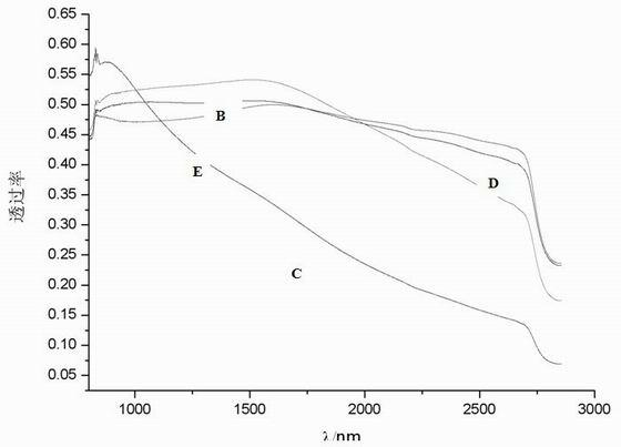
[0040] In this example, the effect of the thickness of the metal layer on the infrared radiation performance i...

Embodiment 3

[0042] Dielectric layer 1 (SnO 2 ), the sputtering time is 6 minutes, and the thickness is 46.44nm; followed by the barrier layer 1, the sputtering time of the barrier layer 1 is NiOx——14s, CrOx——6s, and the thickness is NiOx——2nm, CrOx——1nm; Furthermore, the transition layer (Ni) is plated, the sputtering time of the transition layer is 3.5s, and the thickness is 6nm; then the metallic silver layer is plated, the sputtering time of the metallic silver layer is 4s, and the thickness is 13.12nm. The metal layer is plated at different temperatures, that is, one is plated at 200 ° C, and the other is plated at room temperature; then it is the barrier layer 2, and its plating method and time are the same as before; each film layer is used Plated by magnetron sputtering method. In addition, each film layer is not independent, and their adjacent surfaces penetrate each other, so they have a good bonding force.

[0043] Such as Figure 4 As shown, F represents that the metal layer...


PUM

PropertyMeasurementUnit
Thicknessaaaaaaaaaa
Thicknessaaaaaaaaaa
Thicknessaaaaaaaaaa

Abstract

The invention discloses low emissivity glass. The low emissivity glass contains a glass substrate, a first dielectric layer, a first barrier layer, a transition layer, a metal layer and a second barrier layer in turn from bottom to top, wherein preferably, a second dielectric layer can be plated on the second barrier layer; the transition layer is adopted to promote the growth of the metal layer and ensure that the metal layer can grow to form a continuous structure, thus the glass can have high infrared reflectivity and visible light transmittance; and the barrier layers can fully protect the metal layer to ensure that the high infrared reflectivity of the metal layer can be utilized. The low emissivity glass has low production cost and very good industrial application prospect; and the energy can be effectively saved.

Description

technical field [0001] The invention relates to a low-emissivity glass, which is a coated glass whose surface is coated with multi-layer nano-films so as to transmit visible light and reflect infrared light, ultraviolet light, especially infrared light. It can effectively save energy and is suitable for vehicles and vehicles. Glass used in construction. Background technique [0002] Glass is an indispensable part of buildings, automobiles and other means of transportation. It carries many important functions, such as beautifying the appearance of buildings and automobiles, lighting, bringing a wide view to the interior, and the role of heat preservation or heat insulation. However, the sunlight transmittance of ordinary glass is very high, and the infrared reflectance is very low. Most of the sunlight enters the room through the glass, thereby heating the objects; and when the indoor temperature is higher than the outside world, the heat of these indoor objects will pass thr...

Claims


Application Information

Patent Timeline
IPC IPC(8): C03C17/36
Inventor 朱文仝大利柳慧琼刘喜
Owner HUAZHONG UNIV OF SCI & TECH
Why Eureka
Try Eureka