

Agitator blade for improving leaching rate of metal manganese electrolyte
An electrolyte and metal manganese technology, applied in the field of stirring paddles, can solve problems such as increasing energy consumption, and achieve the effects of reducing energy consumption, low equipment cost and simple structure
Inactive Publication Date: 2011-06-15
CHONGQING UNIV
View PDF3 Cites 13 Cited by
- Summary
- Abstract
- Description
- Claims
- Application Information
AI Technical Summary
Problems solved by technology
As a result of doing so, although some leaching rates can be improved, energy (electricity) consumption will be increased
Method used
View moreImage
Smart ImageViewing Examples

Examples
Embodiment Construction
Login to View More PUM
 Abstract
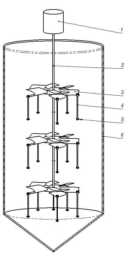
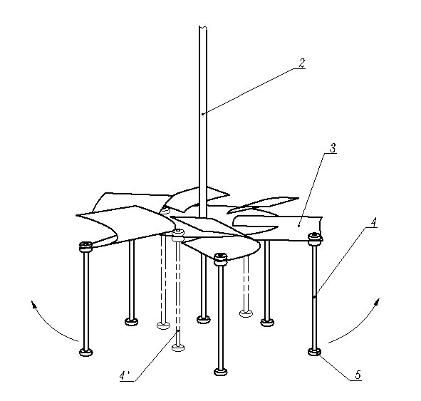
The invention discloses an agitator blade for improving the leaching rate of metal manganese electrolyte. A plurality of layers of agitator blades are arranged, and are fixedly arranged on an agitating shaft coaxial with a leaching groove for the metal manganese electrolyte. The outer end of each agitator blade in each layer of agitator blades is fixedly suspended with a flexible belt; the length of the flexible belt of the agitator blade positioned on the upper layer meets the conditions that: the flexible belt in the vertical state cannot be scratched by the agitator blade on the lower layer, and when the flexible belt is unfolded due to centrifugal force and rotates in ore pulp, the flexible belt cannot be scratched by the side wall of the leaching groove; and the length of the flexible belt of the agitator blade positioned at the lowest layer meets the conditions that: the flexible belt in the vertical state cannot be scratched by a corresponding part at the bottom of the leaching groove, and when the flexible belt is unfolded due to centrifugal force and rotates in the ore pulp, the flexible belt cannot be scratched by the side wall of the leaching groove. The agitator blade can eliminate stirring dead zones under the condition of not increasing energy consumption basically, so the leaching rate of the metal manganese electrolyte can be improved. The agitator blade has the advantages of simple structure and low equipment cost.
Description
Stirring paddle for improving leaching rate of metal manganese electrolyte technical field The invention relates to a stirring paddle in a metal manganese electrolyte leaching tank. Background technique In enterprises that produce electrolytic manganese metal (referred to as electrolytic manganese) by electrolysis, most of them use manganese carbonate (rhodochrosite) as raw material, prepare them into pulp and put them in a leaching tank to leach the electrolyte, and then perform electrolysis. In order to ensure sufficient leaching, stirring paddles for stirring ore pulp are installed in the leaching tanks. The specific structure is that a stirring shaft coaxial with the leaching tank is set in the leaching tank, which is driven by a motor to rotate, and several layers of stirring paddles that are all immersed in the ore pulp are set on the stirring shaft (the number of layers of the stirring paddles According to the depth of the actual leaching tank). When leaching the ...
Claims
Login to View More Application Information
Patent Timeline
 IPC IPC(8): C22B3/02C22B3/04B01F7/18C22B47/00
CPCY02P10/20
Inventor 刘作华宁伟征陶长元孙瑞祥周小霞杜军范兴刘仁龙曾启琴彭浩廖军
Owner CHONGQING UNIV