Fan system and stopping control circuit thereof

A fan system and stop circuit technology, applied in the direction of pump control, circuit devices, electrical components, etc., can solve electromagnetic interference, reduce the working stability of the peripheral circuit of the fan system, and aggravate problems

Active Publication Date: 2013-02-06
SUNONWEALTH ELECTRIC MACHINE IND
View PDF0 Cites 0 Cited by
  • Summary
  • Abstract
  • Description
  • Claims
  • Application Information

AI Technical Summary

Problems solved by technology

[0007] However, generally speaking, the above-mentioned prior art has the following disadvantages, for example: since the current of the motor coil 95 continues to flow when the voltage source VCC is normally powered, when the voltage source VCC is interrupted, due to the potential of the two terminals of the motor coil 95 Equipotential is formed instantaneously, that is, even if the current flowing in the motor coil 95 drops to zero in an instant, a huge induced electromotive force will be established on the motor coil 95 at this moment of change, causing electromagnetic interference; The two ends of 95 are grounded at the same time, so the induced electromotive force established in the motor coil 95 is also instantly reduced to zero, causing the fan system to generate a huge repulsive stress at the moment of stopping, causing the motor vibration and noise to increase, thereby reducing the peripheral circuit of the fan system work stability and reduce the operating life of the fan system

Method used


Image

  • Fan system and stopping control circuit thereof
  • Fan system and stopping control circuit thereof
  • Fan system and stopping control circuit thereof

Examples


Embodiment Construction

[0039] In order to make the above-mentioned and other objects, features and advantages of the present invention more comprehensible, the preferred embodiments of the present invention are specifically cited below, together with the accompanying drawings, and are described in detail as follows:

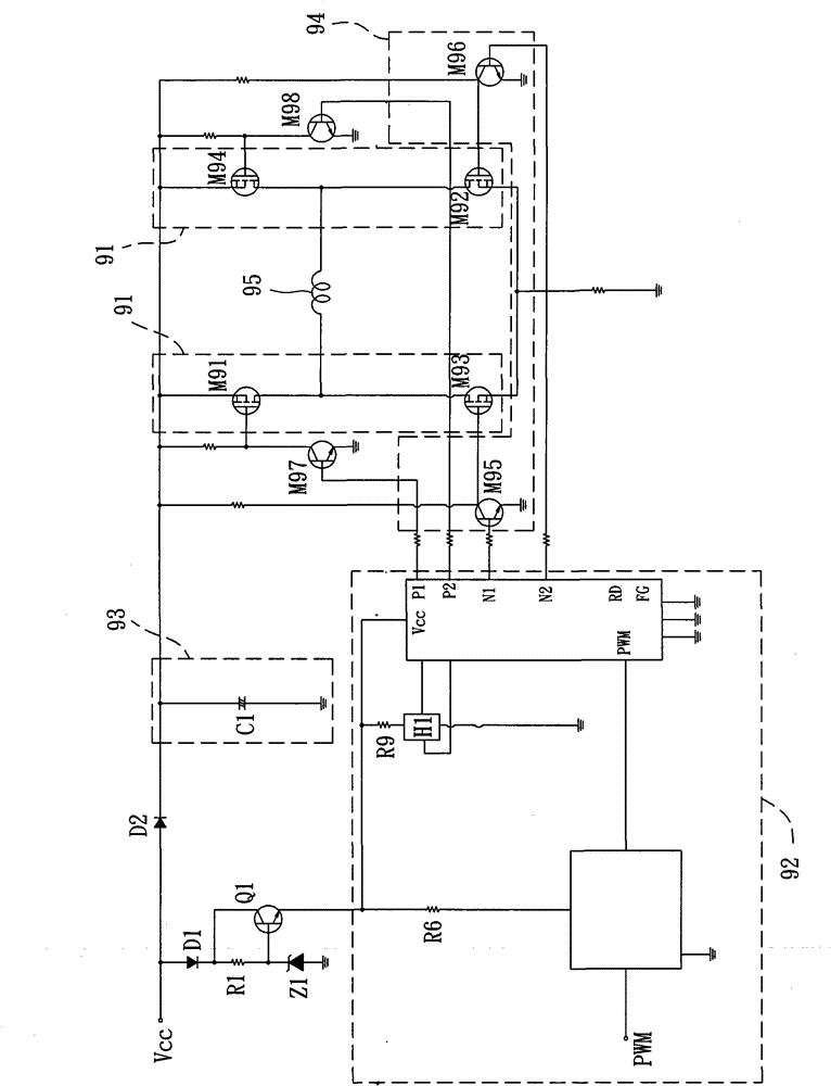
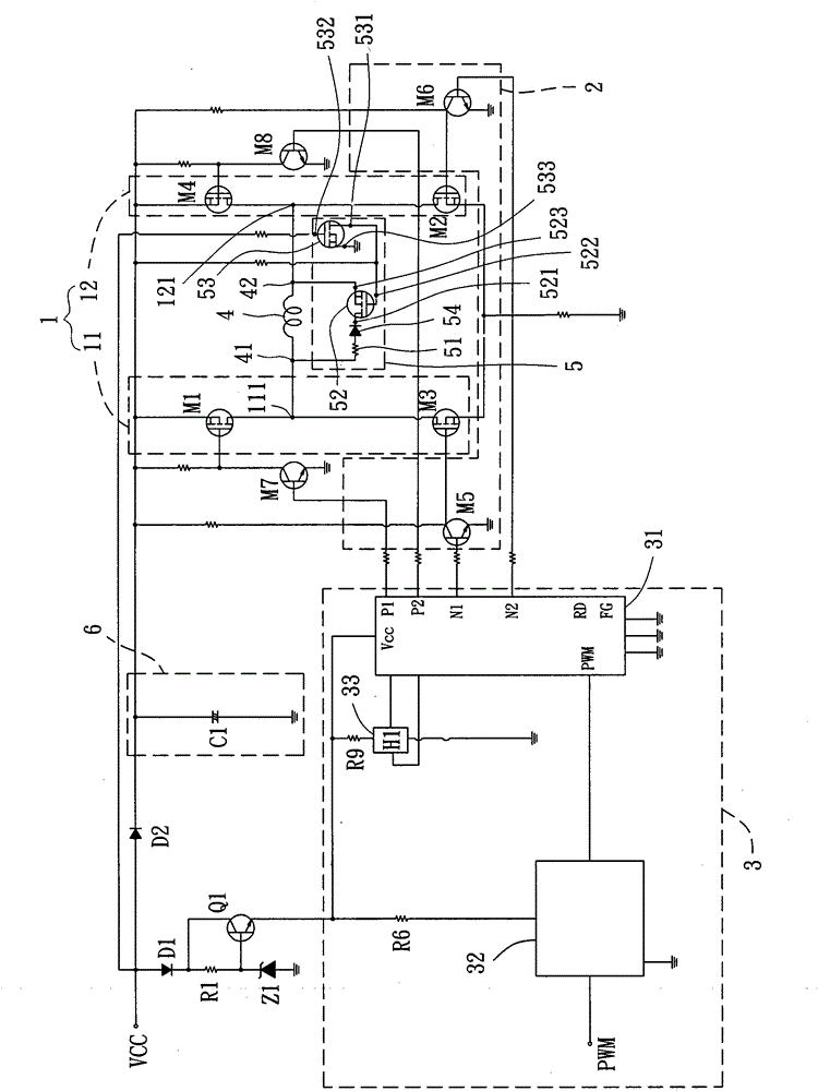
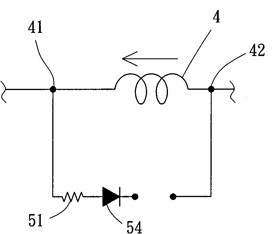
[0040] Please refer to figure 2As shown, it discloses the fan system and its stop control circuit of the first embodiment of the present invention, wherein the fan system includes a drive device 1, a rotation stop circuit 2, a control unit 3, a motor and its coil 4, a buffer Stopping the circuit 5 and an energy storage unit 6 . Wherein the driving device 1, the control unit 3, the energy storage unit 6 and the rotation stop circuit 2 are electrically connected to a voltage source VCC, so that the voltage source VCC can provide the power supply of the above-mentioned components; moreover, the motor The coil 4 is connected to the driving device 1 , and the buffer stop circuit 5 is pref...


PUM


Abstract

The invention discloses a fan system and a stopping control circuit thereof. The fan system comprises a motor coil, an energy storage unit, a driving device and a buffering stopping circuit, wherein the energy storage unit is used for storing electric energy and releasing the electric energy when a voltage source of the fan system is cut off so as to buffer the rotation stopping action of the motor, the driving device is electrically connected with two connecting ends of the motor coil so as to control the direction of current passing through the motor coil, and the buffering stopping circuit is electrically connected with the motor coil; when the voltage source of the fan system is cut off, the buffering stopping circuit is started, a voltage difference is formed on the motor coil, and the motor coil releases electric energy for the buffering stopping circuit and further enables the fan system to stop running slowly in a controllable stopping time.

Description

technical field [0001] The present invention relates to a fan system and its stop control circuit, in particular to a stop control circuit which utilizes a buffer stop circuit to control the fan system to stop running gently. Background technique [0002] In recent years, the use of a digital microcontroller (Micro-Controller Unit, MCU) combined with a power electronic switch drive circuit to design electronic products has become a commonly used technology in the industry. However, when operating the electronic product, the digital microcontroller and the power electronic switch will cause the electronic product to generate a lot of heat due to high frequency operation; therefore, the heat dissipation requirement of the electronic product will become a very important design issue. [0003] At present, the more common heat dissipation method uses the operation of the fan system to drive the wind and heat dissipation of the electronic product. However, based on the considerati...

Claims


Application Information

Patent Timeline
Patent Type & Authority Patents(China)
IPC IPC(8): F04D25/08F04D27/00H02J9/00
Inventor 洪银树陈同安蔡政男吴昆典侯冠印
Owner SUNONWEALTH ELECTRIC MACHINE IND
Why Eureka
Try Eureka