Buffer oil cylinder

A technology of cushioning cylinders and oil holes, applied in the field of hydraulic cylinders, can solve problems such as insignificant deceleration effect, insufficient cushioning effect, and related mechanical damage, and achieve the effects of easy promotion and use, good cushioning effect and long service life

Inactive Publication Date: 2011-06-15
CHANGAN UNIV
View PDF6 Cites 6 Cited by
  • Summary
  • Abstract
  • Description
  • Claims
  • Application Information

AI Technical Summary

Problems solved by technology

Some oil cylinders are used in very harsh environments, and the impact pressure is high. In order to reduce the impact, it is necessary to install a buffer device in the structure of the oil cylinder; When the driving object performs fast reciprocating action, it has a large momentum. In this way, at the end of the stroke, if the piston and the end cover mechanically collide, a large impact and noise will be generated. The generation of this mechanical impact will not only cause the oil cylinder The damage of each p

Method used


Image

  • Buffer oil cylinder
  • Buffer oil cylinder
  • Buffer oil cylinder

Examples


Example Embodiment

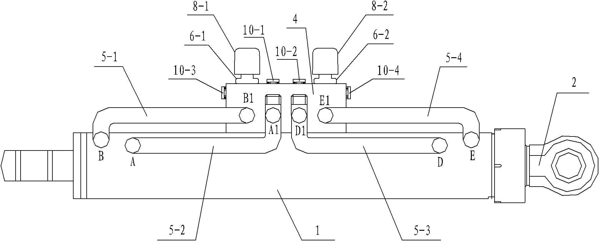
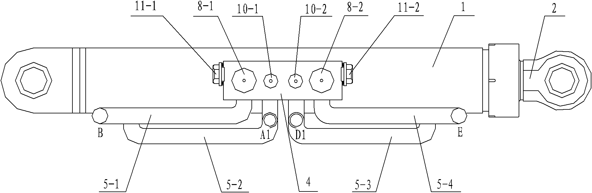
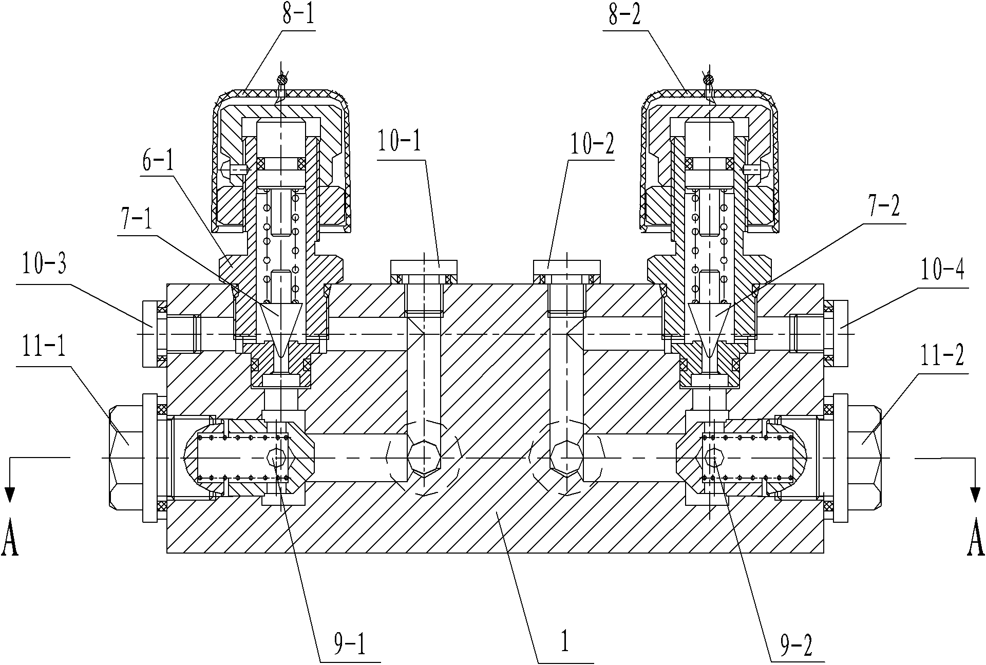
[0031] Such as Figure 1-Figure 4 As shown, the present invention includes a cylinder 1, a piston rod 2 arranged in the cylinder 1, and a piston 3 connected to the piston rod 2 and matched with the inner cavity of the cylinder 1. The two ends of the cylinder 1 are respectively arranged There are oil holes A and oil holes D. The two ends of the cylinder block 1 are also provided with oil holes B and E respectively. The distance between the two oil holes at the same end of the cylinder block 1 is smaller than the width of the piston 3. The top of the cylinder block 1 is provided with a valve block 4, the front of the valve block 4 is provided with an oil hole B1, an oil hole A1, an oil hole D1 and an oil hole E1, and the back of the valve block 4 is provided with an oil hole C and Oil hole F, said oil hole B is connected to oil hole B1 through oil pipe one 5-1, said oil hole A is connected to oil hole A1 through oil pipe two 5-2, and said oil hole D is connected to oil hole B1 th...


PUM


Abstract

The invention discloses a buffer oil cylinder. The buffer oil cylinder comprises a cylinder body, a piston rod and a piston, wherein the two ends of the cylinder body are provided with oil holes A, B, D and E; a valve block is arranged on the top of the cylinder body; oil holes B1, A1, D1 and E1 are formed on the front surface of the valve block; oil holes C and F are formed on the back surface of the valve block; the oil holes B, A, D and E are connected with the oil holes B1, A1, D1 and E1 through an oil pipe 1, an oil pipe 2, an oil pipe 3 and an oil pipe 4 respectively; the oil holes A1 and C are communicated and the oil holes D1 and F are communicated in the valve block; a columnar shell 1 and a columnar shell 2 are arranged on the top of the valve block; a cone valve 1 is arranged in the columnar shell 1; a rotary knob 1 is arranged on the top of the columnar shell 1; a cone valve 2 is arranged in the columnar shell 2; a rotary knob 2 is arranged on the top of the columnar shell2; and the two sides of the valve block are provided with a one-way valve 1 and a one-way valve 2. The buffer oil cylinder has a novel and reasonable design, long service life and a good using effect, is convenient to realize, use, operate and popularize, and is not limited by space during installation.

Description

technical field [0001] The invention belongs to the technical field of hydraulic oil cylinders, in particular to a buffer oil cylinder. Background technique [0002] With the development of hydraulic technology, the use of actuator hydraulic cylinders is becoming more and more common. Some oil cylinders are used in very harsh environments, and the impact pressure is high. In order to reduce the impact, it is necessary to install a buffer device in the structure of the oil cylinder; When the driving object performs fast reciprocating action, it has a large momentum. In this way, at the end of the stroke, if the piston and the end cover mechanically collide, a large impact and noise will be generated. The generation of this mechanical impact will not only cause the oil cylinder The damage of each part, and the damage that seriously affects the piping, various valves, and other related machinery, is very harmful. However, the buffer oil cylinders disclosed in the prior art fo...

Claims


Application Information

Patent Timeline
IPC IPC(8): F15B15/08F15B15/22
Inventor 杨士敏常秋红鲁坦王华忠李玄吴昭军蔡顶春姚泽光
Owner CHANGAN UNIV
Why Eureka
Try Eureka