Potential energy storage type protruding undercarriage buffer

A landing gear buffer and protrusion technology, which is applied in the direction of shock absorbers, shock absorbers, gas-hydraulic shock absorbers, etc., can solve the problem that dust easily pollutes the working environment of the landing gear, the working reliability cannot be guaranteed, and the weight of the landing gear increases and other problems, to achieve the effects of obvious protrusion effect, short protrusion time and reliable work

Active Publication Date: 2011-06-15
NANJING UNIV OF AERONAUTICS & ASTRONAUTICS
View PDF5 Cites 37 Cited by
  • Summary
  • Abstract
  • Description
  • Claims
  • Application Information

AI Technical Summary

Problems solved by technology

The device needs to be equipped with a certain amount of explosives and a complex control system, and the energy generated by the explosion is not easy to control, and the dust generated...

Method used


Image

  • Potential energy storage type protruding undercarriage buffer
  • Potential energy storage type protruding undercarriage buffer
  • Potential energy storage type protruding undercarriage buffer

Examples


Embodiment Construction

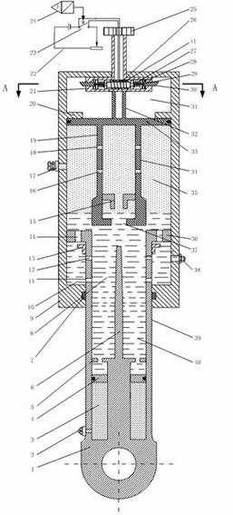
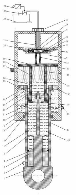
[0011] As attached figure 1 Shown is a schematic diagram of the structure of the potential energy storage type protruding landing gear bumper bar before it is compressed downwards. The piston rod 1 is sleeved in the outer cylinder 9 from the bottom of the outer cylinder 9, moves axially relative to the outer cylinder 9 and is sealed with it; the piston rod 1 is fixed to the upper end of the piston rod outer cylinder by a variable section oil needle 6, a piston rod outer cylinder 39 and The outer wall of the piston rod 39 is formed with an upper oil hole 12 and a lower oil hole 11, the annular piston 36 is provided with an oil return hole 14, and the outer wall of the piston rod 39 has an upper oil hole 12 There is also an oil return hole throttle valve 13 installed on the upper side; the inner lower end of the piston rod outer cylinder 39 is also installed with a high-pressure chamber floating piston 4 and a retaining ring 5 that limits the highest position of the high-pressure ...


PUM


Abstract

The invention discloses a potential energy storage type protruding undercarriage buffer, and belongs to airplane undercarriage buffers. The buffer comprises an outer cylinder (9), a piston rod (1), a central oil hole support (19), a pressure rod (25) and a limiting device (21). A control cavity (31) is formed above a middle supporting surface (33) and below the top of the outer cylinder (9); a low-pressure air cavity (35) is formed between the top of oil (40) and the middle supporting surface (33); a main oil cavity (8) is formed in the interior and the upper part of a piston rod outer cylinder (39) positioned on the upper part of a high-pressure cavity floating piston (4); an annular protruding oil cavity (10) is formed among an annular piston (36), the outside wall of the piston rod outer cylinder (39) and the inner wall of the outer cylinder (9); and a high-pressure air cavity (3) is formed between the high-pressure cavity floating piston (4) and the bottom of the piston rod outer cylinder (39). The buffer has the characteristics of short protruding time, good protruding effect, easiness for control and simple structure, and can be used for a land-based airplane taking off in short distance.

Description

Technical field [0001] The invention belongs to a landing gear buffer of a catapult take-off carrier aircraft. technical background [0002] In order to reduce the plane's dependence on large airports and enable the plane to take off smoothly with limited or quickly repaired runways in wartime, the short take-off performance of the plane has received great attention. Especially for carrier-based aircraft, the largest deck that can be used for take-off of an aircraft carrier is only about 100 m. A good short-range take-off capability is the basic guarantee for completing a variety of combat missions. After the carrier-based aircraft’s short-distance taxiing, the ship’s departure speed cannot provide enough lift to overcome the aircraft’s own weight. In addition, the loss of ground effect after leaving the ship causes the carrier’s aircraft to sink in track after leaving the ship, and it is easy to fall. Sea accident. In order to ensure the flight safety of carrier-based aircraft...

Claims


Application Information

Patent Timeline
IPC IPC(8): F16F9/06F16F9/34F16F9/32
Inventor 聂宏崔俊华段萍萍万峻麟张明
Owner NANJING UNIV OF AERONAUTICS & ASTRONAUTICS
Why Eureka
Try Eureka