Eureka AIR delivers breakthrough ideas for toughest innovation challenges, trusted by R&D personnel around the world.

Three-dimensional fixing method of micro-naked coupling lens

A technology of coupling lens and fixing method, which is applied in the coupling of optical waveguide, etc., can solve the problems of affecting assembly yield, unable to measure optical coupling efficiency in real time, large optical coupling loss, etc., and achieve good control, small error, and easy operation Effect

Inactive Publication Date: 2011-06-15
大连艾科科技开发有限公司
View PDF5 Cites 5 Cited by
  • Summary
  • Abstract
  • Description
  • Claims
  • Application Information

AI Technical Summary

Problems solved by technology

An alignment error of 10 microns can cause a large enough optical coupling loss
In addition, the passive (Passive) alignment method cannot measure the optical coupling efficiency in real time
Once the assembly is completed, it is found that the optical coupling loss is too large and cannot be repaired, which will directly affect the yield of the assembly

Method used


Image

  • Three-dimensional fixing method of micro-naked coupling lens
  • Three-dimensional fixing method of micro-naked coupling lens
  • Three-dimensional fixing method of micro-naked coupling lens

Examples


Embodiment Construction

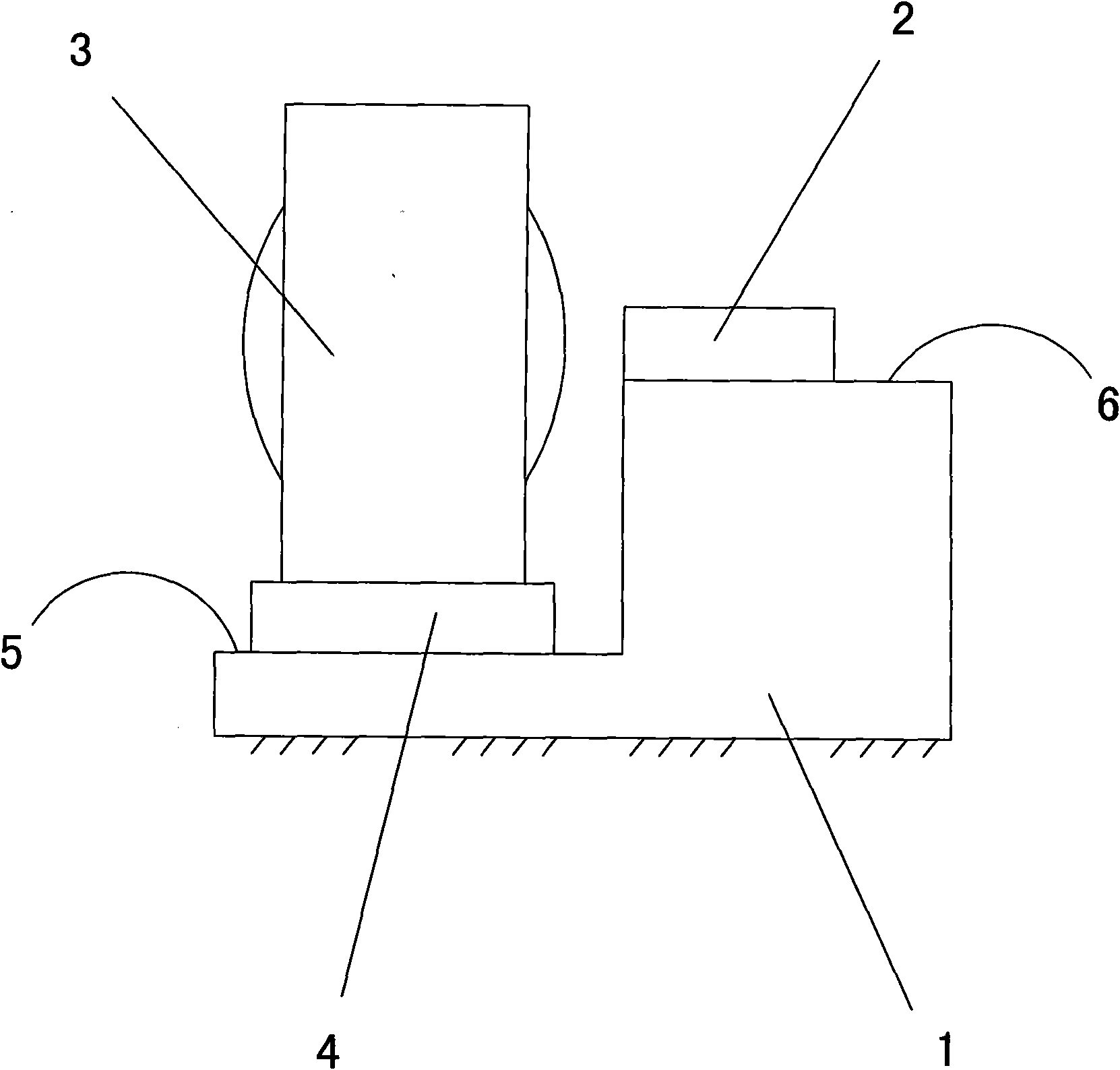
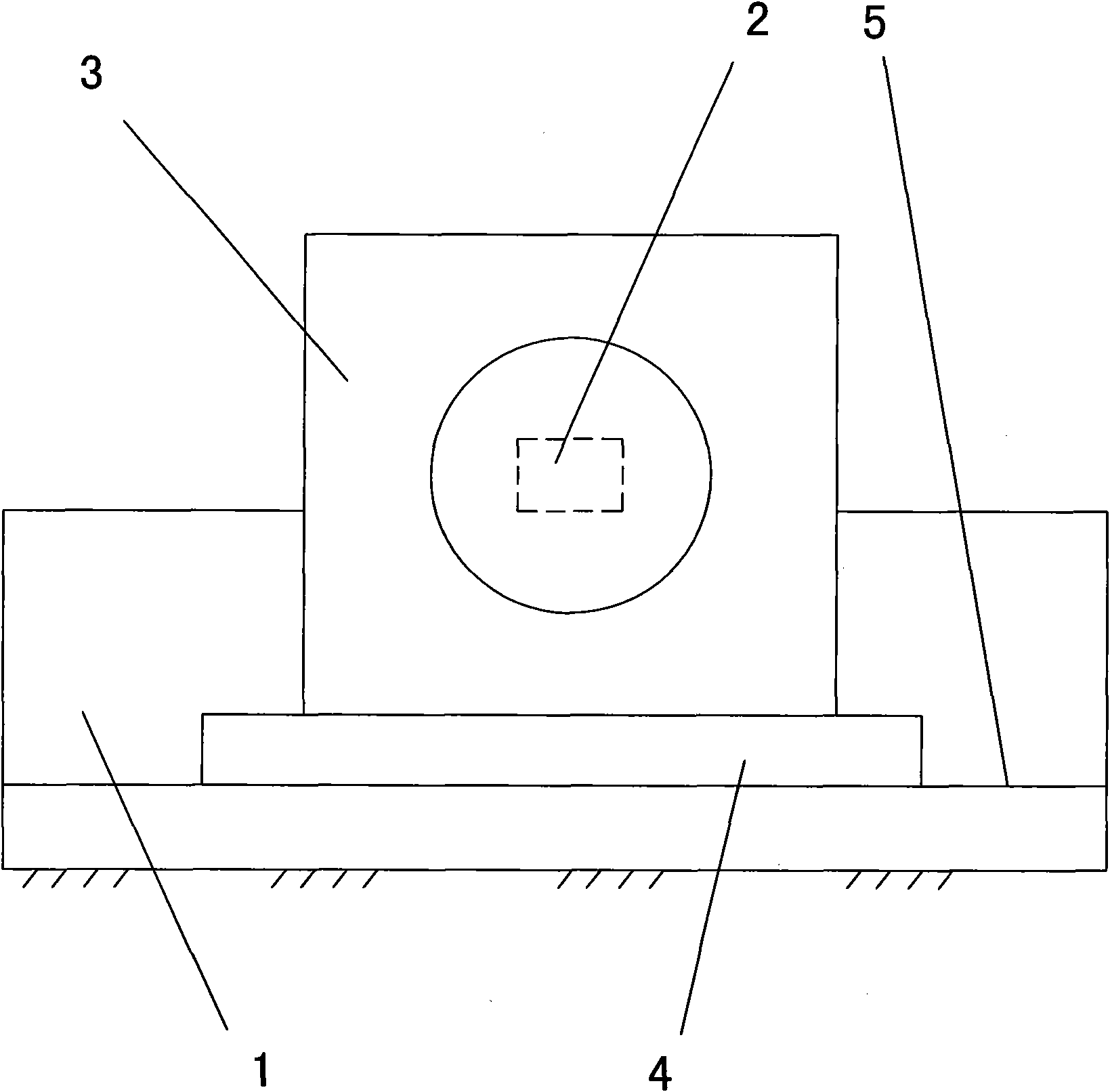
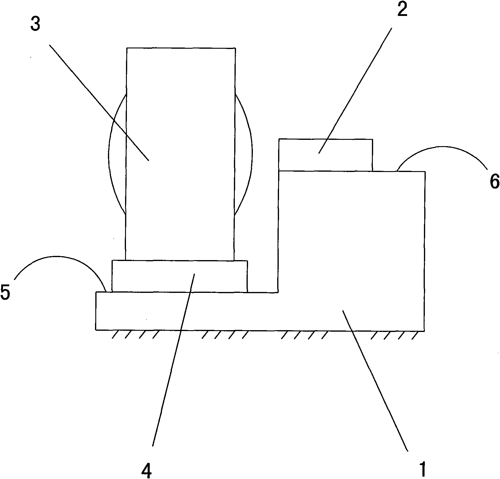
[0013] Such as figure 1 , 2 Shown: 1 is a step seat, there is a top support surface 6 above the rear side of the step seat 1, and the front side of the step seat 1 is at the bottom of and parallel to the bottom support surface 5 of the top support surface 6.

[0014] The steps of the present invention are as follows:

[0015] a. Paste the LD chip 2 on the top support surface 6 above the step seat 1, the front side of the step seat 1 has a bottom support surface 5 lower than and parallel to the top support surface 6;

[0016] b. Suspend the tiny bare coupling lens 3 above the bottom support surface 5 using a straw-type fixture, and adjust the position of the tiny bare coupling lens 3 through the straw-type fixture, so that the tiny bare coupling lens 3 is coupled with the LD chip 2 in place;

[0017] c, utilize the CCD camera to measure the gap height between the bottom surface of the tiny bare coupling lens 3 and the bottom support surface 5 from the side;

[0018] d. Move...


PUM


Abstract

The invention provides a three-dimensional fixing method of a micro-naked coupling lens, comprising the steps: attaching an LD (laser diode) chip on a top supporting surface on a step seat, wherein the front side of the step seat is provided with a bottom supporting surface which is lower than and parallel to the top supporting surface; utilizing a suction pipe type clamp to hang the micro-naked coupling lens above the bottom supporting surface and adjusting the position of the micro-naked coupling lens by the suction pipe type clamp so as to lead the coupling of the micro-naked coupling lens and the LD chip to be in place; utilizing a CCD (charged coupled device) camera to measure the height of a gap between the bottom surface and the bottom supporting surface of the micro-naked coupling lens; utilizing the suction pipe type clamp to move the micro-naked coupling lens upwards, then selecting and putting a gasket on the bottom supporting surface, and moving the micro-naked coupling lens downwards to lead the micro-naked coupling lens to be located on the gasket, wherein the thickness of the gasket is consistent to the height of the measured gap; and utilizing the conventional sticking mode to fix the micro-naked coupling lens and the gasket. The three-dimensional fixing method has the advantages that the operation is simple and convenient, the control is easy, the error is less, the optical coupling efficiency is high, the time and the labor are saved, and simultaneously the repairability is achieved.

Description

technical field [0001] The invention relates to a three-dimensional fixing method of a lens, in particular to a three-dimensional fixing method of a tiny naked coupling lens. Background technique [0002] In recent years, the size of optoelectronic devices has become smaller and smaller. In order to reduce the volume, the coupling lens generally uses a tiny bare lens. But the bare lens cannot be fixed on the metal bracket with YAG laser because there is no metal sleeve. So far, the alignment and fixation of tiny bare lenses are all using the passive (Passive) alignment method, that is, on the Si Micro Bench with a processing accuracy of 1-2 microns and a V-groove, first paste it with sub-micron precision by a manipulator. The LD chip then places the tiny bare lens in the proper position of the V groove, and finally fixes it with solder or UV glue. The alignment and fixing method not only requires expensive assembly machines and Si Micro Bench with V-groove, but also the co...

Claims


Application Information

Patent Timeline
Patent Type & Authority Applications(China)
IPC IPC(8): G02B6/42
Inventor 张耐刘伟
Owner 大连艾科科技开发有限公司
Why Eureka
Eureka Blog
Learn More