Liquid crystal injection method
A liquid crystal and injection machine technology, applied in nonlinear optics, instruments, optics, etc., can solve problems such as inability to accurately monitor liquid crystal temperature, reduce liquid crystal viscosity, etc., reduce product scrap rate, reduce liquid crystal loss, and have a simple and practical heating structure Effect
Active Publication Date: 2011-06-15
CHANGSHA YUSHUN DISPLAY TECH
View PDF7 Cites 7 Cited by
- Summary
- Abstract
- Description
- Claims
- Application Information
AI Technical Summary
Problems solved by technology
The purpose of the present invention is to solve the problem that the temperature of the liquid crystal cannot be accurately monitored and the viscosity of the liquid crystal cannot be reduced to the greatest extent, and to provide a liquid crystal injection method by directly heating the liquid crystal cell
Method used
View moreImage
Smart ImageViewing Examples
Examples
Embodiment Construction
Login to View More PUM
 Abstract
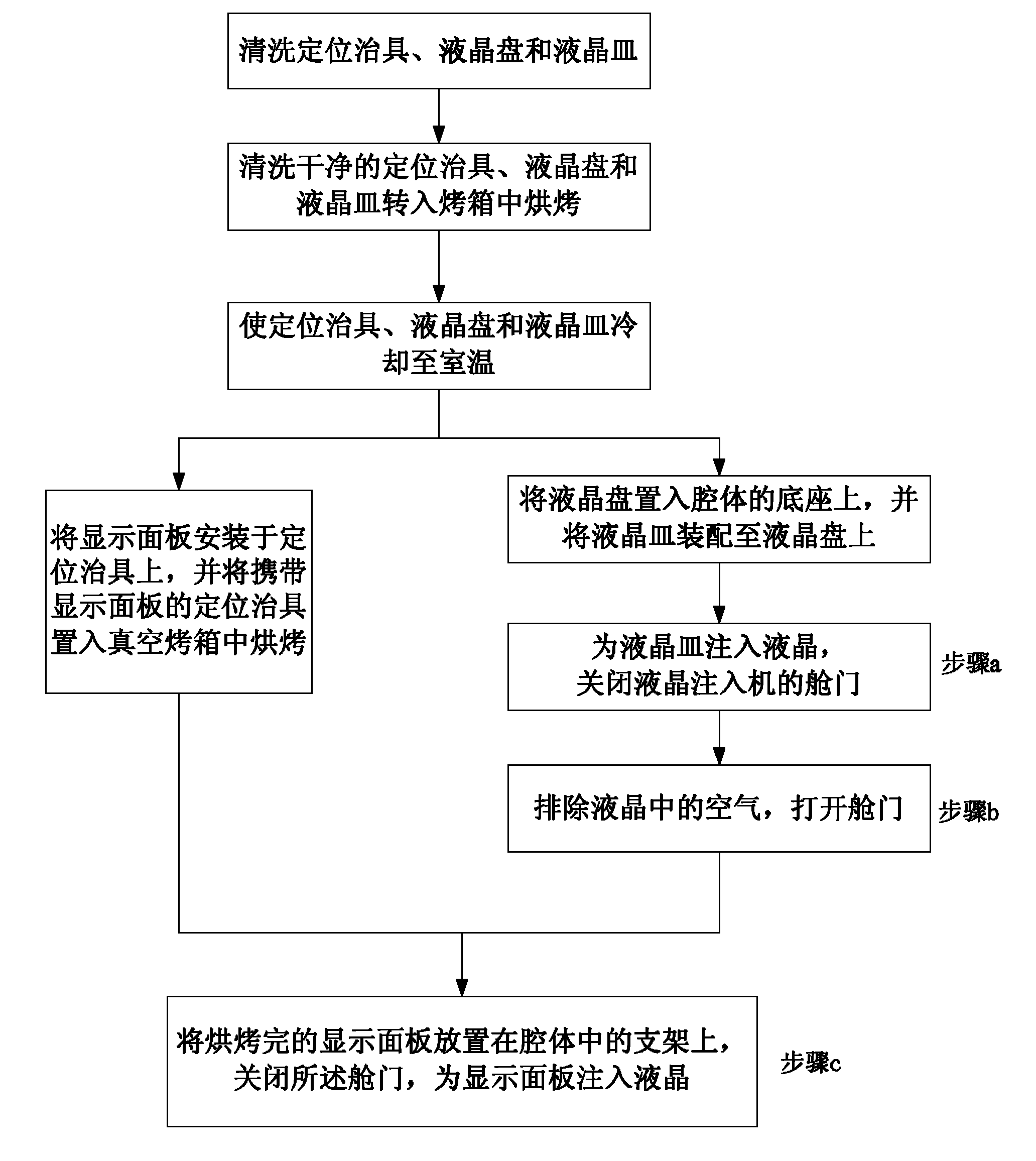
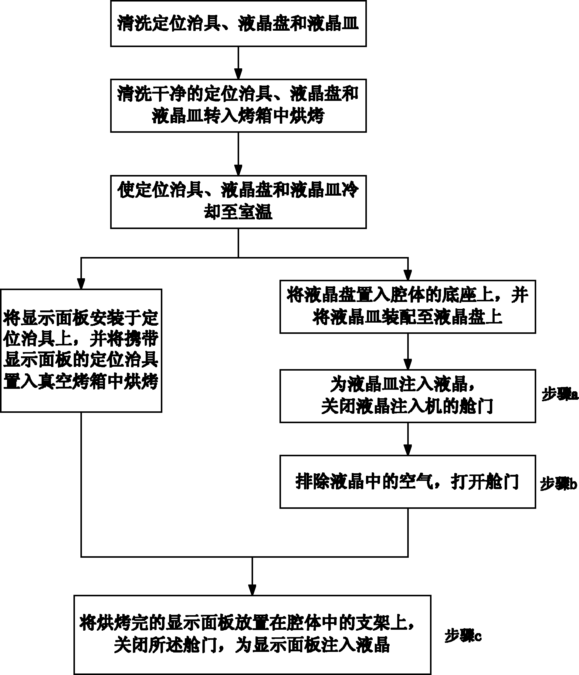
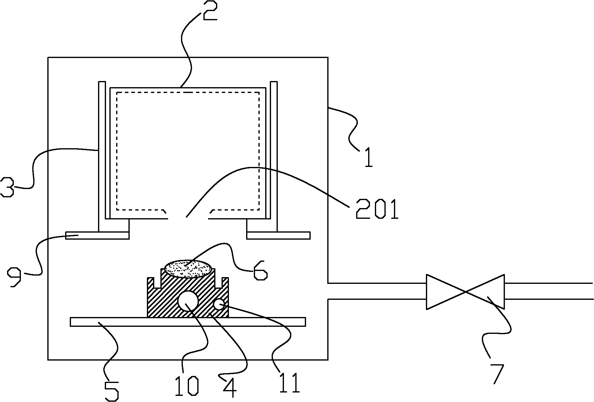
The invention discloses a liquid crystal injection method, comprising the following steps of: step a, closing the cabin door of a liquid crystal injection machine when a liquid crystal container is filled with liquid crystal, and then implementing step b, wherein the liquid crystal container is arranged on a base within a cavity of the liquid crystal injection machine, the liquid crystal container is equipped, in an insertion manner, with a liquid crystal heater controlled by an electric control system and a liquid crystal temperature controller which is used for feeding back liquid crystal temperature collected in real time to the electric control system to form a closed loop control; step b, removing air from the liquid crystal, then opening the cabin door and implementing step c; and step c, placing a roasted display panel on a bracket which is arranged within the cavity, and then closing the cabin door to complete the steps for injecting liquid crystal into the display panel. The liquid crystal injection method provided by the invention has the advantages that the heating structure of the liquid crystal container is simple and practical, the temperature of the liquid crystal can be accurately monitored, the viscosity of the liquid crystal is reduced to the largest extent while preventing the volatilization of low-boiling point component in the liquid crystal, and the consumption of the liquid crystal and the rejection rate of the product are reduced.
Description
A liquid crystal injection method technical field The invention relates to a method for injecting liquid crystals into glass empty boxes used in the production of liquid crystal displays. The liquid crystal injection method involved in the invention is mainly used in the injection process of ordinary low-viscosity liquid crystals, especially for some high-viscosity liquid crystals , and the injection process of ordinary low-viscosity liquid crystals under the condition of low ambient temperature. Background technique Liquid crystal display (LCD) is a kind of electronic device that achieves the purpose of controlling the light passing through the liquid crystal layer by controlling the rotation of liquid crystal molecules in an electric field, and finally realizes graphic display under the synergy of polarizing plates. The structure of the liquid crystal display mainly includes two glass substrates with transparent electrodes engraved on the surface, an alignment film coate...
Claims
Login to View More Application Information
Patent Timeline
 IPC IPC(8): G02F1/1341
Inventor 杨顺林舒晖佘光全
Owner CHANGSHA YUSHUN DISPLAY TECH
Features
- R&D
- Intellectual Property
- Life Sciences
- Materials
- Tech Scout
- Unparalleled Data Quality
- Higher Quality Content
- 60% Fewer Hallucinations
Learn More Browse by: Latest US Patents, China's latest patents, Technical Efficacy Thesaurus, Application Domain, Technology Topic, Popular Technical Reports.
© 2025 PatSnap. All rights reserved.Legal|Privacy policy|Modern Slavery Act Transparency Statement|Sitemap|About US| Contact US: help@patsnap.com


