Cutter path generating method for double blade head processing of turbine long blade profile

A tool track and double cutter head technology, applied in the field of mechanical processing, can solve the problems of controlling cutting force, increasing blade processing deformation, and not reflecting double-knife processing, so as to achieve the effect of improving processing efficiency and increasing processing efficiency

Inactive Publication Date: 2011-06-15
XI AN JIAOTONG UNIV
View PDF4 Cites 10 Cited by
  • Summary
  • Abstract
  • Description
  • Claims
  • Application Information

AI Technical Summary

Problems solved by technology

If the method of generating the tool path with a single tool is used to determine the tool position control point data of the double-knife machining, although the geometric error requirements can be met, the corresponding relationship between the tools on both sides cannot be determined, and the advantages of the double-knife machining cannot be reflected.
[0011] The general tool path generation methods only meet the requirements of machining error from the perspective of geometric relationship, but do not take into account the influence of tool path on cutting force
Most of the methods that consider the influence of cutting force only improve the influence of cutting force by changing the feed rate, and do not control the cutting force from the perspective of generating tool position control point data.
When the tool path is generated by double-knife machining, if the influence of the cutting force is not considered, the offset effect of the cutting force of the generated tool path may not be ideal. If it is not considered properly, it may even increase the possibility of blade machining deformation

Method used


Image

  • Cutter path generating method for double blade head processing of turbine long blade profile
  • Cutter path generating method for double blade head processing of turbine long blade profile
  • Cutter path generating method for double blade head processing of turbine long blade profile

Examples


Embodiment Construction

[0045] The present invention is described in further detail below in conjunction with accompanying drawing:

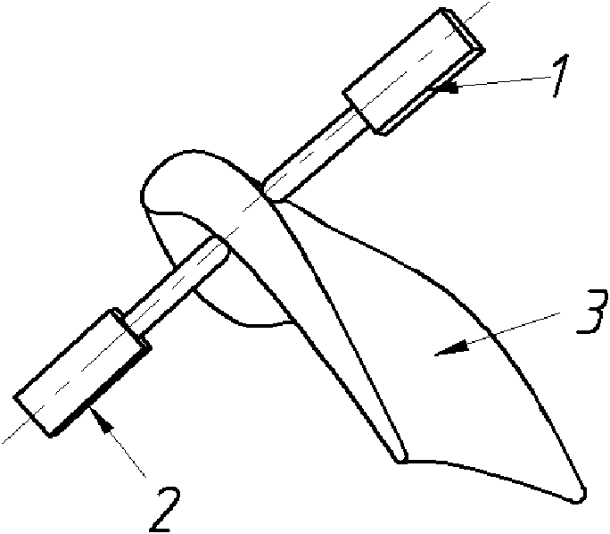
[0046] refer to figure 1 , the working principle of the double-cutter head processing blade is as follows: during processing, the spindle head 1 and the spindle head 2 with the cutter move on both sides of the profile of the blade 3 to be processed. The movement of the two spindle heads is controlled by two separate kinematic mechanisms and coordinated by the overall control system.

[0047] The specific implementation steps of the tool path planning method for double-knife machining are as follows:

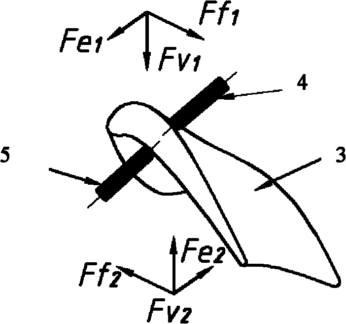
[0048] 1) Establish cutting force model

[0049] Firstly, the corresponding mathematical relationship between the cutting force and the inclination angle of the blade machining tool axis is established, and the cutting force model of blade machining is obtained. Since the tool path planning for double-knife machining is based on the cutting force model, it is very impo...


PUM


Abstract

The invention discloses a cutter path generating method for double blade head processing of a turbine long blade profile. The method comprises the following steps: firstly establishing a corresponding mathematical relation between cutting force and cutter shaft inclinations during blade processing so as to obtain a cutting force model of the blade processing; then acquiring section moulded line data of a blade, and determining the range of cutter location control point data of double blades in the section moulded lines of the blade, wherein the cutter location control point data comprise the step length between cutter location control points, the number of the cutter location control points and the cutter shaft inclination of a cutter at each corresponding cutter location control point; and finally determining the final offset effect of the cutting force. In the invention, the double blade head can simultaneously process parts, and the processing efficiency is obviously improved compared with a single blade by reasonably scheduling the processing technique on the parts; and besides, the double blade processing can ensure the cutting force to be greatly offset, thus the processing deformation of the parts is obviously reduced.

Description

technical field [0001] The invention belongs to the technical field of mechanical processing, and relates to the processing of long blade profiles of steam turbines, in particular to a method for generating tool tracks for double-cutter machining of long blade profiles of steam turbines. Background technique [0002] Steam turbine blades are generally composed of blade roots, blade body, shrouds, tie bars and transition parts. The root of the blade is the fixed part of the blade, and the body of the blade is the part of the blade with the blade shape. The quality of the blade shape directly determines the working quality of the blade and the performance of the steam turbine. The working environment of the blade is harsh, and it bears the centrifugal force brought by high temperature, high pressure and high speed and the corrosion of high temperature steam. In order to ensure the performance of the steam turbine and the safety of the equipment, the material of the steam turb...

Claims


Application Information

Patent Timeline
Patent Type & Authority Applications(China)
IPC IPC(8): G05B19/19
Inventor 赵万华位文明董襄阳余常武卢秉恒
Owner XI AN JIAOTONG UNIV
Why Eureka
Try Eureka