Modular reconfigurable robot
A reconfigurable robot and modular technology, applied in the direction of manipulators, program-controlled manipulators, manufacturing tools, etc., can solve problems affecting development and application, flexibility, reliability and practical constraints of modular reconfigurable robots, and achieve The effect of rich module types, clean appearance and easy positioning
- Summary
- Abstract
- Description
- Claims
- Application Information
AI Technical Summary
Problems solved by technology
Method used
Image
Examples
Embodiment 1
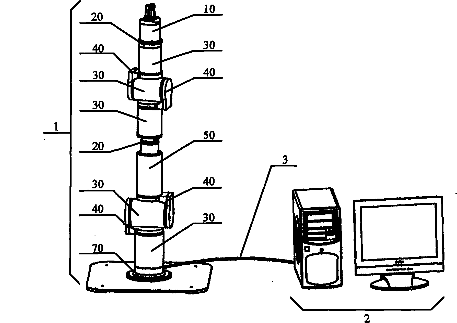
[0102] Embodiment 1: as figure 1 As shown, a modular reconfigurable robot includes a host computer 2 and a robot 1, the robot 1 is connected to the CAN communication interface card of the host computer 2 through a CAN bus 3, and the robot 1 includes a base module, a gripper Modules and multiple alternately connected joint modules and link modules between the two, the user can combine them into a variety of configuration robots 1 with 2 to 7 degrees of freedom according to the task and environmental needs, wherein: the base module is connected to the joint module, The gripper module is connected to the link module, and each module is equipped with a power supply / signal bus for electrical connection, and the action of the robot 1 is controlled by the host.
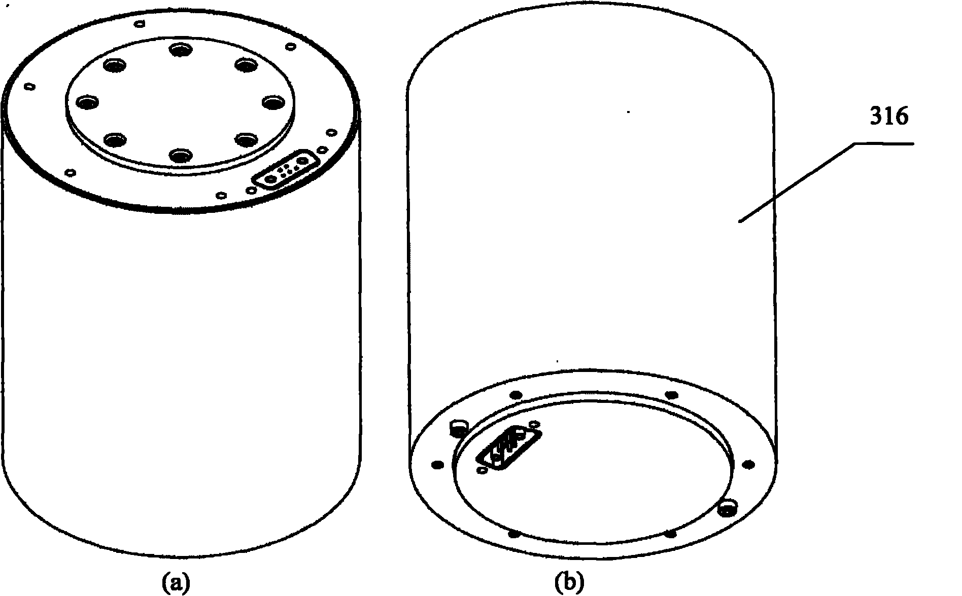
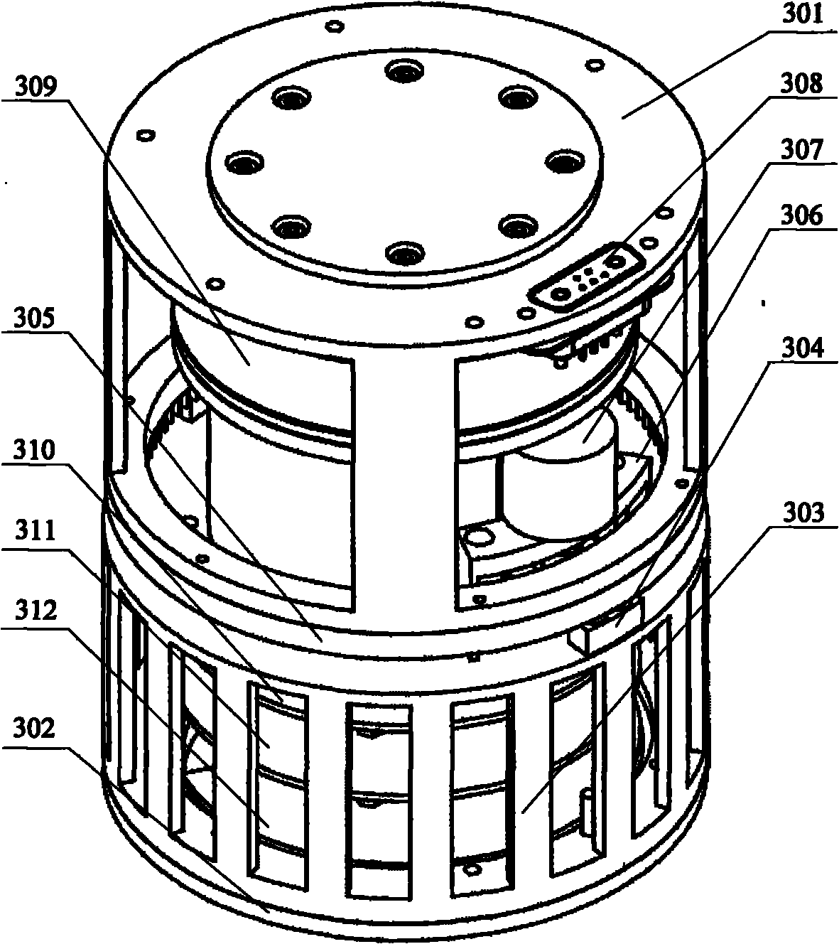
[0103] The joint module is divided into a rotary joint module 30 and a telescopic joint module 50 ; the link module is divided into a linear link module 20 , a right-angle link module 40 and a parallel link module 60 .
[0...
Embodiment 2
[0118] Embodiment 2: as Figure 29 As shown, the robot in this example uses a fixed base module 70 to connect the first rotary joint module 30, the first right-angle link module 40, the second rotary joint module 30, the parallel link module 60, and the third rotary joint module in sequence. Module 30, the second right-angle link module 40, the fourth rotary joint module 30, the third right-angle link module 40, the fifth rotary joint module 30, the fourth right-angle link module 40, the sixth rotation The joint module 30 , the linear link module 20 and the gripper module 10 constitute a robot structure with 6 degrees of freedom.
[0119] The rotary joint module 30 , the linear link module 20 , the right-angle link module 40 , the fixed base module 70 and the jaw module 10 described in this example are all the same in structure as those in the first embodiment. Such as Figure 8 (a) As shown in (b), the parallel connecting rod module 60 is provided with a third protective co...
Embodiment 3
[0120] Embodiment 3: as Figure 30 As shown, the robot in this example uses a fixed base module 70 to connect the first rotary joint module 30, the first right-angle link module 40, the second rotary joint module 30, the parallel link module 60, and the third rotary joint module in sequence. The module 30 , the second right-angle link module 40 and the gripper module 10 constitute a robot structure with three degrees of freedom.
[0121] The structure of the fixed base module 70 , the rotary joint module 30 , the right-angle link module 40 , the parallel link module 60 and the jaw module 10 described in this example is the same as that in the second embodiment.
PUM
 Abstract
Description
Claims
Application Information
 - R&D
- Intellectual Property
- Life Sciences
- Materials
- Tech Scout
- Unparalleled Data Quality
- Higher Quality Content
- 60% Fewer Hallucinations
Browse by: Latest US Patents, China's latest patents, Technical Efficacy Thesaurus, Application Domain, Technology Topic, Popular Technical Reports.
© 2025 PatSnap. All rights reserved.Legal|Privacy policy|Modern Slavery Act Transparency Statement|Sitemap|About US| Contact US: help@patsnap.com


