Rotational joint module of modularized reconfigurable robot

A technology for reconstructing robots and rotating joints, applied in manipulators, manufacturing tools, joints, etc., can solve the problems of not considering braking and mechanical limit, low precision, complicated connection and installation, etc., to achieve auxiliary position measurement and connection. And the effect of accurate positioning and increasing output torque

Active Publication Date: 2011-06-22
SHENYANG INST OF AUTOMATION - CHINESE ACAD OF SCI
View PDF0 Cites 19 Cited by
  • Summary
  • Abstract
  • Description
  • Claims
  • Application Information

AI Technical Summary

Problems solved by technology

Among the various types of rotary joint modules currently developed, most of them adopt the transmission scheme of DC motor plus planetary deceleration, which has a large hysteresis and low precision; the mechanical interface has no positioning design, and the connection and installation are complicated; the wiring of the electrical interface is exposed outside, and the robot It is easy to cause wires to be entangled during movement; brakes and mechanical limits are not considered, and safety during use is ignored; incremental code discs are commonly used, and position information cannot be retained when power is accidentally turned off, and robot status data will be lost when power is turned on again. missing, cannot continue
The existence of the above problems directly affects the motion control performance of the rotary joint module and reduces the flexibility, reliability and practicability of the modular reconfigurable robot

Method used


Image

  • Rotational joint module of modularized reconfigurable robot
  • Rotational joint module of modularized reconfigurable robot
  • Rotational joint module of modularized reconfigurable robot

Examples


Embodiment Construction

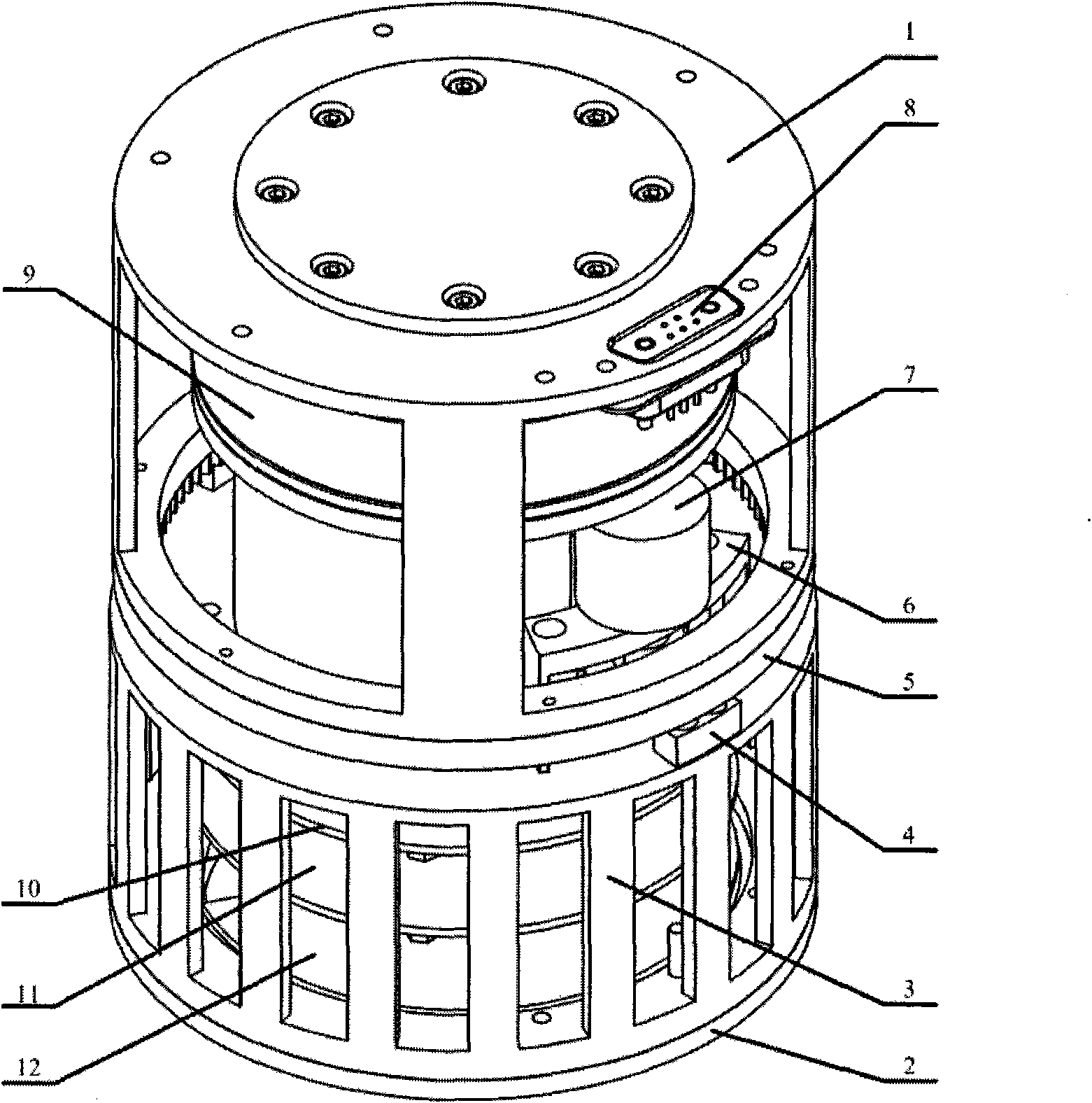
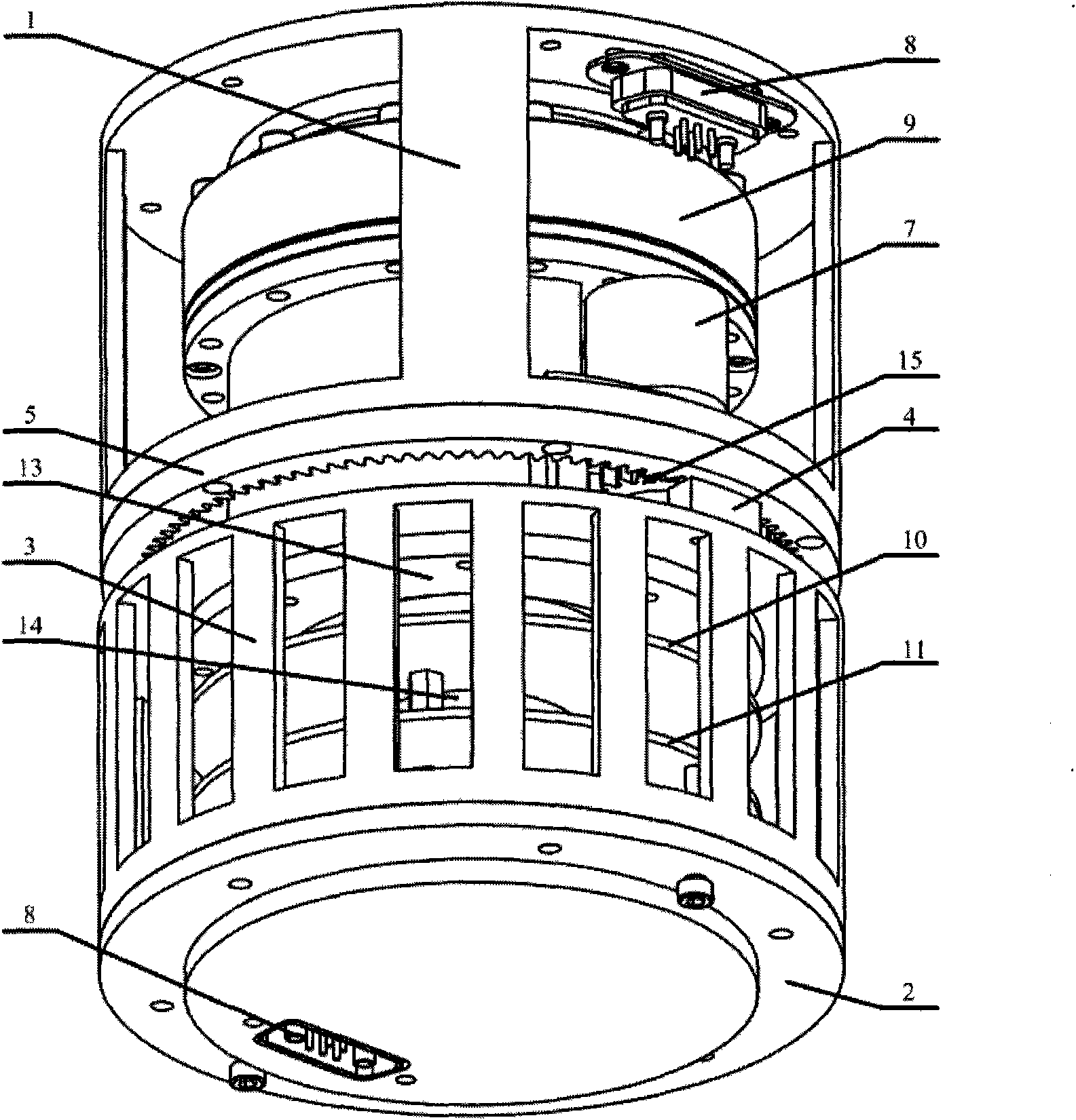
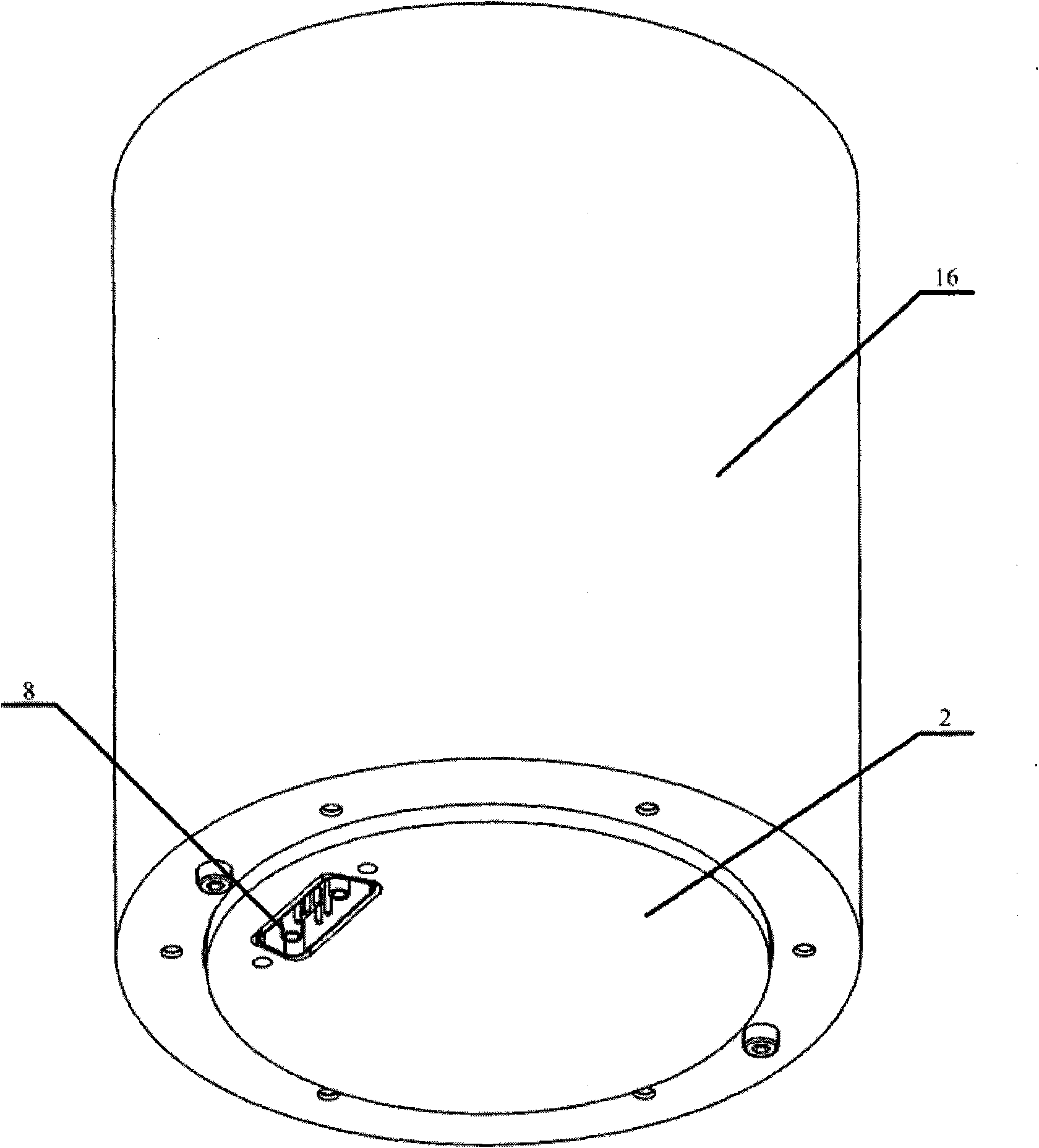
[0035] The present invention will be further described below in conjunction with the accompanying drawings.

[0036] refer to Figure 1 to Figure 14 , the present invention includes a cage support 3, an upper end cover 1, a lower end cover 2, a DC brushless motor 18, a planetary reducer 17, an electromagnetic brake 19, an incremental code disc 20, and also includes a harmonic reducer 9, a rotary potential Meter 7, pinion 15, ring gear 5, including mechanical limiter and electrical limiter, DSP control circuit board, drive circuit board, power conversion circuit board, D-type connector, outer cover, and the upper end cover 1 is installed on The output end of the harmonic reducer 9, the harmonic reducer 9 is installed on the cage support 3, the output shaft of the planetary reducer 17 is installed at the input end of the harmonic reducer 9, the planetary reducer 17 is installed on the cage support 3, the front output shaft of the DC brushless motor 18 is installed at the input ...


PUM


Abstract

The invention discloses a rotational joint module of a modularized reconfigurable robot. On the basis of planetary reduction, one level of harmonic reduction is added on motor output, a reduction ratio is improved, an output torque is added, and the transmission precision of the module is improved. An upper end cover and a lower end cover serve as installation joints, the flange-type design with locating seam allowances and pin holes is adopted, and the module is accurately and conveniently connected and located. All electric wires are arranged in a cage-type support, the upper end cover and the lower end cover and are isolated and protected by an outer cover, thereby avoiding the problem that the electric wires are coiled when a robot moves. Mechanical limit and electric limit are arranged in the module. On the basis of adopting an incremental coded disc, a rotating potentiometer is added to measure the assistant position of module movement, absolute position information is recorded under the condition of accidental power failure, and the system can continuously work after being electrified. The rotational joint module has the advantages of reasonable and simple structure, high precision and inner routing, is convenient to install and position and is safe and reliable to use.

Description

technical field [0001] The invention relates to a modular reconfigurable robot. Background technique [0002] The modular reconfigurable robot is composed of a series of modules such as joints and connecting rods with different sizes and functional characteristics. It can change the overall structure and recombine through simple and fast assembly and disassembly between modules in the way of building blocks. Shaped robot. Compared with traditional fixed-configuration robots, modular reconfigurable robots can realize "one set of components, multiple configurations", and can choose the best robot structure according to task requirements, so the adaptability and operation of complex environments more capable. [0003] A key technology that embodies the advantages of modular reconfigurable robots is the design of rotary joint modules. Among the various types of rotary joint modules currently developed, most of them adopt the transmission scheme of DC motor plus planetary dece...

Claims


Application Information

Patent Timeline
Patent Type & Authority Applications(China)
IPC IPC(8): B25J17/00
Inventor 王洪光姜勇潘新安佘岑何能
Owner SHENYANG INST OF AUTOMATION - CHINESE ACAD OF SCI
Why Eureka
Try Eureka