Isokinetic smoke dust sampling device and sampling method

A sampling device, smoke and dust technology, applied in the direction of sampling devices, measuring devices, instruments, etc., can solve the problem of inability to continuously reflect the change of smoke and dust, the inability to meet the requirements of on-site process adjustment in stages, and the inability of the air pump to achieve constant-speed pumping, etc. problem to achieve the effect of preventing test abort

Inactive Publication Date: 2011-06-22
MAANSHAN IRON & STEEL CO LTD
View PDF2 Cites 11 Cited by
  • Summary
  • Abstract
  • Description
  • Claims
  • Application Information

AI Technical Summary

Problems solved by technology

[0002] GB / T16157-1996 "Determination of Particulate Matter in Exhaust from Stationary Pollution Sources and Sampling Methods of Gaseous Pollutants" stipulates the single-gun equal-velocity smoke sampling and measurement method, but as far as the converter flue gas wet dust removal process in the iron and steel industry is concerned, it has certain limitations. Limitations: ①The fan inlet is under high negative pressure (above -16kPa), high dust content (150mg / Nm 3 Above) and high water content conditions, the dust content measurement is carried out in a long oxygen blowing cycle (about 15min), the dust collection filter cartridge is quickly blocked by dust and water, and the air pump cannot achieve constant speed air extraction. Caused the test to be suspended; ②Single-gun equal-velocity smoke sampling method can only detect the average smoke concentration during the test period at one time, cannot continuously reflect the change of smoke and dust in each time period, and cannot meet the requirements of on-site process adjustment in stages

Method used


Image

  • Isokinetic smoke dust sampling device and sampling method
  • Isokinetic smoke dust sampling device and sampling method

Examples


Embodiment Construction

[0033] Below with reference to the accompanying drawings, through the description of the embodiments, the specific embodiments of the present invention, such as the mutual position and connection relationship between the various parts involved, are further described in detail, so as to help those skilled in the art to understand the conception of the present invention , Technical solutions have a more complete, accurate and in-depth understanding.

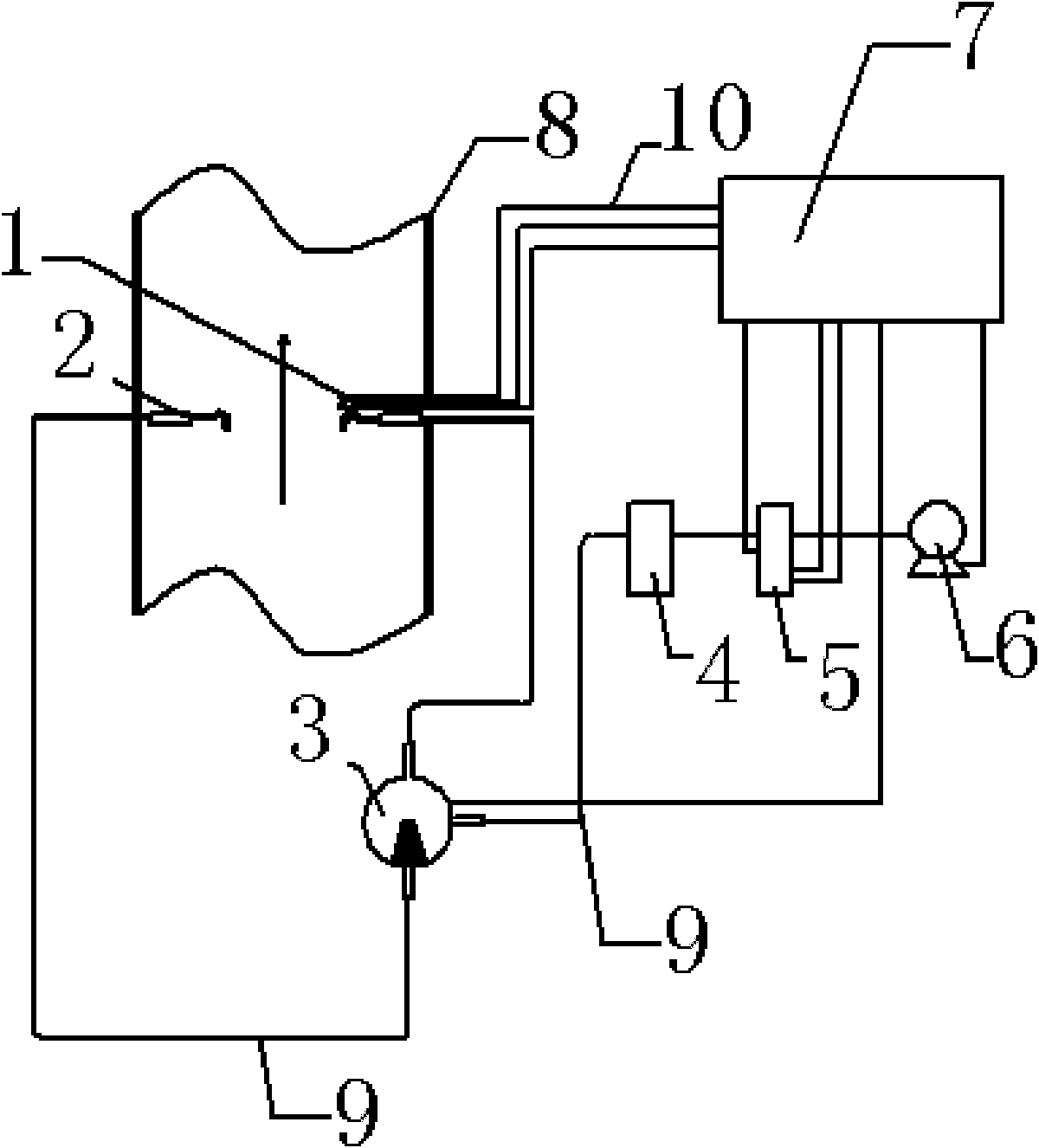
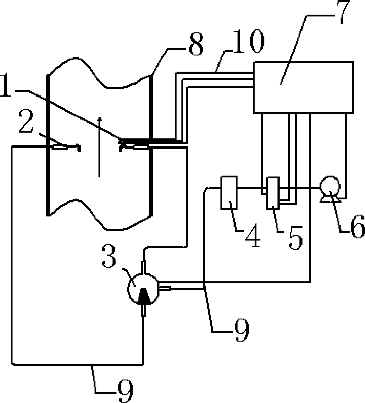
[0034] Such as figure 1 As shown, the constant-velocity smoke sampling device includes a main sampling gun 1, an auxiliary sampling gun 2, a three-way switching valve 3, a flow meter 5, an air pump 6, a flue 8 and a single-chip microcomputer 7.

[0035] The main sampling gun 1 and the auxiliary sampling gun 2 are arranged inside the flue 8 .

[0036] The main sampling gun 1 is connected to the first port of the three-way switching valve 3 through a smoke hose 9 .

[0037] The secondary sampling gun 2 is connected to the second po...


PUM


Abstract

The invention discloses an isokinetic smoke dust sampling device and a sampling method. The isokinetic smoke dust sampling device comprises a main sampling gun, a subsidiary sampling gun, a three-way switching valve, a flowmeter, an aspirator pump, a flue and a singlechip, wherein, the main sampling gun and the subsidiary sampling gun are arranged in the flue; the main sampling gun is connected with the first port of the three-way switching valve through a smoke hose; the subsidiary sampling gun is connected with the second port of the three-way switching valve through a smoke hose; the third port of the three-way switching valve is connected with one end of the flowmeter through a smoke hose; the other end of the flowmeter is connected with the aspirator pump through a smoke hose; and the main sampling gun, the three-way switching valve, the flowmeter, the aspirator pump and the singlechip are connected through signal connecting lines. The sampling method of the isokinetic smoke dust sampling device comprises six steps. By the device and method provided by the invention, the dust content measurement under the working conditions of high negative pressure, high dust content and high water containing content can be realized, and the detection data in each stage can be provided in primary detection, thus providing the basis for adjusting the process in stages.

Description

technical field [0001] The invention relates to the fields of thermal engineering and environmental protection detection in the iron and steel industry, in particular to an isokinetic smoke sampling device and a sampling method. Background technique [0002] GB / T16157-1996 "Determination of Particulate Matter in Exhaust from Stationary Pollution Sources and Sampling Methods of Gaseous Pollutants" stipulates the single-gun equal-velocity smoke sampling and measurement method, but as far as the converter flue gas wet dust removal process in the iron and steel industry is concerned, it has certain limitations. Limitations: ①The fan inlet is under high negative pressure (above -16kPa), high dust content (150mg / Nm 3 Above) and high water content conditions, the dust content measurement is carried out in a long oxygen blowing cycle (about 15min), the dust collection filter cartridge is quickly blocked by dust and water, and the air pump cannot achieve constant speed air extraction...

Claims


Application Information

Patent Timeline
Patent Type & Authority Applications(China)
IPC IPC(8): G01N1/24G01K13/12G01N15/06
Inventor 周劲军陈广言
Owner MAANSHAN IRON & STEEL CO LTD
Why Eureka
Try Eureka