Ball bladder sampling device and sampling method

A sampling device and bulb technology, applied to the sampling device and other directions, can solve the problems of deflagration, long sampling time, poor real-time performance, etc., and achieve the effects of safe sampling requirements, low cost of use, and short sampling period

Active Publication Date: 2011-06-22
MAANSHAN IRON & STEEL CO LTD
View PDF3 Cites 8 Cited by
  • Summary
  • Abstract
  • Description
  • Claims
  • Application Information

AI Technical Summary

Problems solved by technology

However, the single-head bladder gas extraction method has the following defects in use: 1. The sampling time (the time required to complete a bladder sampling) is longer, because the bladder is set for a single air inlet (air outlet), in order to eliminate Due to the influence of residual gas, the bladder must be self-cleaned before collection, that is, the bladder is filled and emptied. Generally, the number of self-cleaning times is more than 4 times. For high-purity tests, the number of cleaning times is more, resulting in a sampling time of more than 3 minutes. ; 2. The real-time performance is poor. Due to the uncertainty of sampling time, the real-time representativeness of sampling is poor under fluctuating working conditions; 3. There are potential safety hazards. For poisonous and harmful gases such as gas, the bladder quickly There are deflagration and poisoning possibilities in the process of cleaning and discharging, threatening personal and equipment safety; 4. The influence of air introduction cannot be ruled out at all, because the air inlet is connected to the atmosphere when the single-headed bladder is connected to the air, causing air to be brought in. Affects sampling accuracy, especially for high-purity gases

Method used


Image

  • Ball bladder sampling device and sampling method
  • Ball bladder sampling device and sampling method
  • Ball bladder sampling device and sampling method

Examples


Embodiment Construction

[0027] In the following, referring to the accompanying drawings, through the description of the embodiments, the specific implementation of the present invention, such as the mutual position and connection relationship between the various parts involved, the function and working principle of each part, the operation and use method, etc., will be further detailed. Descriptions are provided to help those skilled in the art have a more complete, accurate and in-depth understanding of the concept and technical solutions of the present invention.

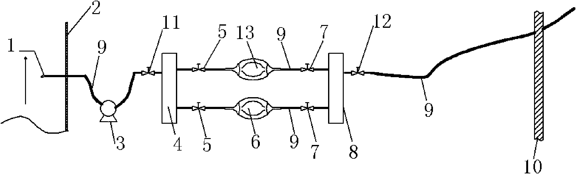
[0028] Such as figure 1 As shown, the bladder sampling device includes a flue 2, a sampling gun 1 located at the cross section of the flue 2, an air extraction and pressurization pump 3 connected to the sampling gun 1, and an air inlet connected to the air extraction and pressurization pump 3. Air collecting pipe 4, the bladder connected with air intake collecting pipe 4, the exhaust collecting pipe 8 connected with the bladder, and the ...


PUM


Abstract

The invention discloses a ball bladder sampling device and a sampling method. The ball bladder sampling device comprises a flue (2), a sampling gun (1), a sucking pressure pump (3), an air intake and collecting pipe (4), a ball bladder, an air exhaust and collecting pipe (8) and an air sampling hose (9), wherein the sampling gun (1) is arranged at the section of the flue (2), the sucking pressure pump (3) is connected with the sampling gun (1), the air intake and collecting pipe (4) is connected with the sucking pressure pump (3), the ball bladder is connected with the air intake and collecting pipe (4), the air exhaust and collecting pipe (8) is connected with the ball bladder, and the air sampling hose (9) is connected with the air exhaust and collecting pipe (8) and extends outside a wall body (10). The sampling method utilizing the ball bladder sampling device comprises four steps. The sampling method adopts a way of double-ball-bladder sampling, and the ball bladder always keeps the positive pressure status, does not have a phenomenon of inleakage of air and does not need repeated self cleaning. The sampling period (the time needed by completing one-time ball bladder sampling) adopting the double-head ball bladder is saved by 85% compared with the single-head ball bladder sampling method. On the basis of simple operation and low use cost, the sampling method meets the sampling requirements for real time, accuracy and safety.

Description

technical field [0001] The invention relates to the fields of thermal engineering and environmental protection detection in the iron and steel industry, in particular to a bladder sampling device and a sampling method. Background technique [0002] The manual sampling method using a single-headed bladder for gas extraction has a history of hundreds of years. Due to its easy operation, easy portability, and low cost of use, it is still used in the iron and steel industry for sampling and analysis of gas, combustion flue gas, and special gases. widely used in. However, the single-head bladder gas extraction method has the following defects in use: 1. The sampling time (the time required to complete a bladder sampling) is longer, because the bladder is set for a single air inlet (air outlet), in order to eliminate Due to the influence of residual gas, the bladder must be self-cleaned before collection, that is, the bladder is filled and emptied. Generally, the number of self-c...

Claims


Application Information

Patent Timeline
Patent Type & Authority Applications(China)
IPC IPC(8): G01N1/24
Inventor 周劲军陈广言
Owner MAANSHAN IRON & STEEL CO LTD
Why Eureka
Try Eureka