Driving circuit of stepping motor

A stepping motor and drive circuit technology, applied in the direction of motor generator control, electrical components, control systems, etc., can solve the problem of low torque

Active Publication Date: 2011-06-22
SANYO ELECTRIC CO LTD +2
View PDF5 Cites 0 Cited by
  • Summary
  • Abstract
  • Description
  • Claims
  • Application Information

AI Technical Summary

Problems solved by technology

Especially in the initial stage of rotation, it is necessary to provide high torque, but it is also possible to make the torque low in the state of rotation holding of continuous rotation

Method used


Image

  • Driving circuit of stepping motor
  • Driving circuit of stepping motor
  • Driving circuit of stepping motor

Examples


Embodiment Construction

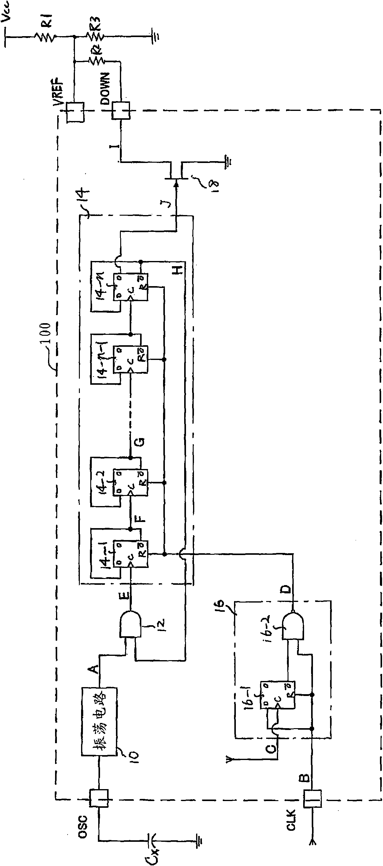
[0019] Such as figure 1 As shown, the stepping motor drive circuit 100 according to the embodiment of the present invention is configured to include an oscillation circuit 10 , an AND element 12 , a shift register 14 , a reset circuit 16 and a switching element 18 . It is preferable that the driving circuit 100 is formed in one semiconductor chip together with the basic driving circuit of the stepping motor.

[0020] The oscillation circuit 10 oscillates at a frequency corresponding to the capacitance value of a capacitor Cx connected to an external terminal OSC, and outputs an oscillation clock signal A. The oscillating clock signal A is input to the AND element 12 .

[0021] The "AND" element 12 receives the oscillating clock signal A and the inverted output Q of the flip-flop 14-n of the last stage of the shift register 14, and the flip-flop 14-n of the last stage of the oscillating clock signal A and the shift register 14 When the inverted output Q of n is high level, t...


PUM


Abstract

The invention provides a driving circuit of a stepping motor. A control signal for switching a reference voltage for setting the current of the stepping motor is prevented from being generated by an external device. The driving circuit of the stepping motor is internally provided with a shift register (14), a resetting circuit (16) and a switching element (18), wherein the shift register (14) receives a transmitter clock signal (A), shifts according to the transmitter clock signal (A) and outputs a gate signal (J) a set time later after resetting; the resetting circuit (16) outputs a resetting signal (D) for resetting the shift register (14) after receiving an input stepping signal (B) for driving the stepping motor; and the switching element (18) receives the gate signal (J) of the shift register (14) and switches a cut-off state and a on-state.

Description

technical field [0001] The invention relates to a driving circuit of a stepping motor. Background technique [0002] In order to rotationally drive a stepping motor, it is necessary to provide torque. In particular, it is necessary to provide high torque at the initial stage of rotation, but it is also possible to make the torque low in the rotation holding state of continuous rotation. Therefore, there is an advantage in that power consumption can be reduced by performing control to reduce the energizing current flowing to the stepping motor in the rotation holding state. In order to switch the energized current, it is necessary to switch the current setting reference voltage of the drive circuit of the stepping motor. [0003] Figure 5 The configuration of a conventional stepping motor drive circuit is shown. In the initial stage of rotation, switch S1 is turned off to set the reference voltage VREF for current setting to be higher. In the rotation holding state, switc...

Claims


Application Information

Patent Timeline
IPC IPC(8): H02P8/14
Inventor 本木义人岛崎努伍远杰
Owner SANYO ELECTRIC CO LTD
Why Eureka
Try Eureka