Gas fuel injection valve

A gas fuel and injection valve technology, applied in the direction of low pressure fuel injection, low pressure fuel injection, fuel injection device, etc., can solve problems such as hindering cost reduction, increase in the number of parts and assembly man-hours, etc., and achieves reduction of assembly man-hours and zero reduction. Number of parts and cost reduction effect

Inactive Publication Date: 2012-11-07
KEIHIN CORP
View PDF5 Cites 0 Cited by
  • Summary
  • Abstract
  • Description
  • Claims
  • Application Information

AI Technical Summary

Problems solved by technology

In such a structure, in order to form a seal groove on the outer periphery of the magnetic cylinder, a pair of ring-shaped members dedicated thereto are required, so the number of parts and assembly man-hours increase, which prevents cost reduction

Method used


Image

  • Gas fuel injection valve
  • Gas fuel injection valve

Examples


Embodiment 1

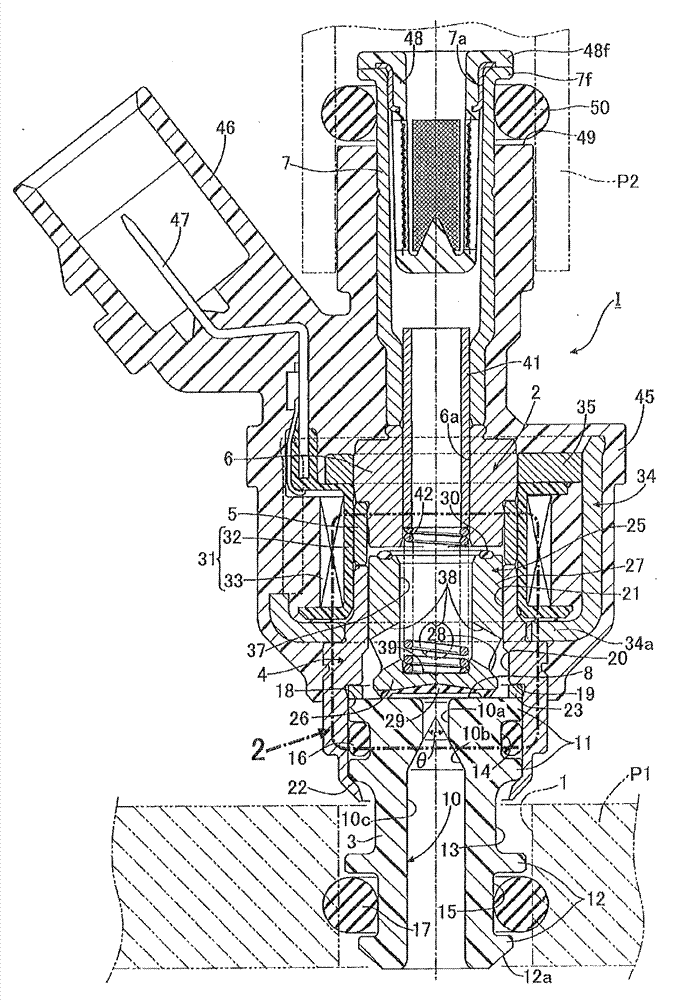
[0024] exist figure 1 Among them, the front end portion of the gas fuel injection valve I is installed in the mounting hole 1 provided in the intake passage member P1 of the engine, and the gas fuel injection valve I can be inserted into the intake passage member P1 during the intake stroke of the engine. Inject gaseous fuel.

[0025] The valve sleeve 2 of the injection valve 1 is formed by coaxially arranging the nozzle member 3, the magnetic cylinder 4, the non-magnetic collar 5, the fixed iron core 6 and the fuel inlet cylinder 7 sequentially from the front end side thereof, and making them interact with each other. Composed of liquid-tight combination.

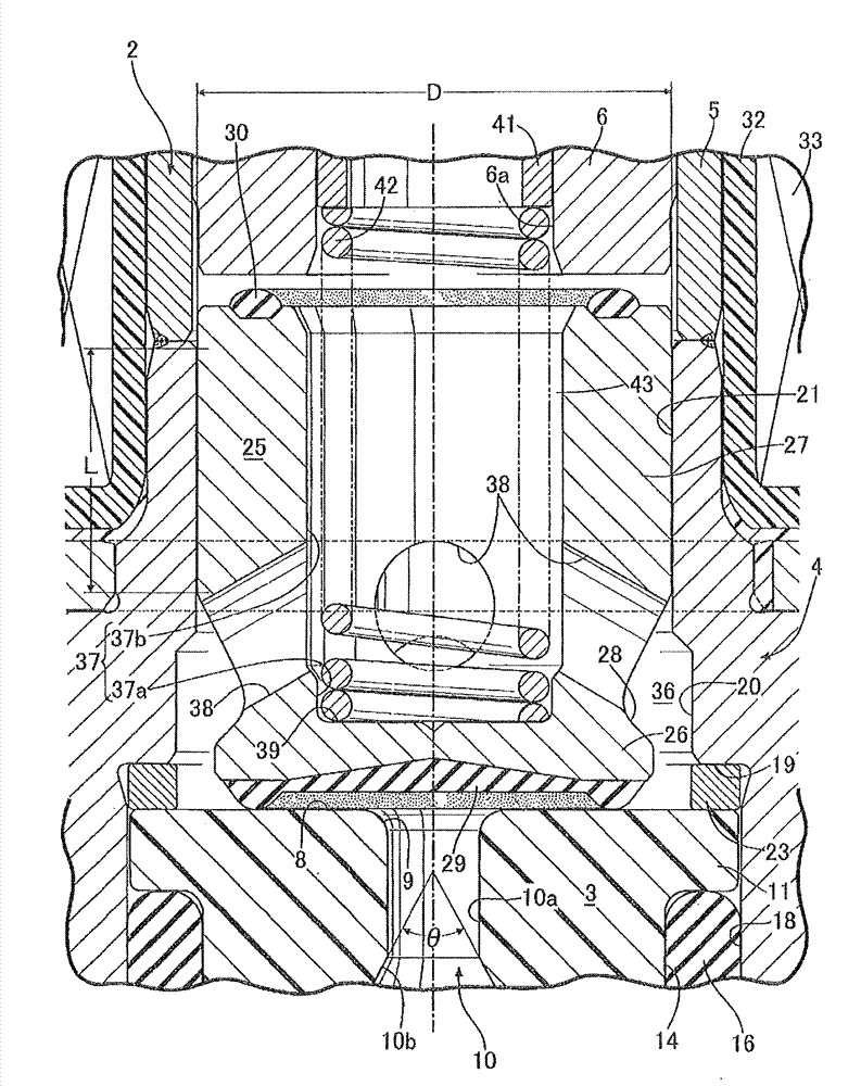
[0026] The nozzle member 3 is made of synthetic resin, and a nozzle hole 10 is formed in the center of the nozzle member 3 , and the rear end surface of the opening of the nozzle hole 10 is formed on the flat valve seat 8 . On the outer periphery of the nozzle member 3, a first fitting portion 11 located at the rear end...


PUM


Abstract

A gas fuel injection valve wherein a valve housing (2) is provided with a nozzle member (3) having a flat valve seat (8) and a nozzle hole (10) penetrating through the center of the valve seat, and also with a magnetic circular tube body (4) joined to the nozzle member (3). The nozzle member (3) consists of a synthetic resin, and on the outer periphery of the nozzle member (3) are formed a first fitting section (11) fitted in a fitting connecting hole (18) in a front end section of the magnetic circular tube body (4), a second fitting section (12) fitted in a mounting hole (1) in an air intake path member (P1) of an engine, and a connecting recess (13) located between both the fitting sections (11, 12). A staking tube section (22) formed at the front end of the magnetic circular tube body(4) is staked to the connecting recess (13) side to join the magnetic circular tube body (4) and the nozzle member (3) together. An annular seal groove (15) in which a seal (17) is mounted is formed in the outer periphery of the second fitting section (12), and the seal (17) makes close contact with the inner peripheral surface of the mounting hole (1) in the air intake path member (P1). Thus, the seal groove in which the seal (17), which makes close contact with the inner peripheral surface of the mounting hole (1) in the air intake path member (P1), is mounted can be formed without using a special ring member.

Description

technical field [0001] The present invention relates to a gas fuel injection valve that uses natural gas such as CNG (compressed natural gas) or LPG (liquefied petroleum gas: Liquefied petroleum gas) as fuel to supply an internal combustion engine. In particular, it relates to a gas fuel injection valve having the following structure Improvement: The valve sleeve has: a nozzle member having a flat valve seat at the front end and a nozzle hole penetrating through the center of the valve seat; a magnetic cylinder combined with the nozzle member; and a fixed The iron core, the fixed iron core is continuously arranged on the rear end side of the magnetic cylinder, the magnetic plunger (plunger) is slidably accommodated in the magnetic cylinder, and the front end of the magnetic plunger is attached with a valve seat capable of seating on the valve seat. The seat part made of elastic material, when the fixed iron core is excited, the magnetic plunger moves, so that the seat part is ...

Claims


Application Information

Patent Timeline
Patent Type & Authority Patents(China)
IPC IPC(8): F02M21/02F02M51/06F02M69/04
CPCY02T10/32F02M21/0266F02M2200/9023F02M69/04F02M21/0278F02M51/0682F02M21/0212F02M51/0667F02M21/0254Y02T10/30
Inventor 泷口直人
Owner KEIHIN CORP
Why Eureka
Try Eureka