Embedded ultrasonic deaeration device and deaeration process

A built-in, defoaming technology, used in spinning solution defoaming, spinning solution filtration, fiber processing, etc., can solve problems such as high energy consumption, long time, fiber damage, etc., to ensure product fiber quality, defoaming The effect of shortened time and shortened dissolution time

Inactive Publication Date: 2012-06-27
TIANJIN POLYTECHNIC UNIV
View PDF0 Cites 0 Cited by
  • Summary
  • Abstract
  • Description
  • Claims
  • Application Information

AI Technical Summary

Problems solved by technology

During the solution spinning process, the defoaming effect of the spinning solution directly affects the quality of the product fiber, and the spinning solution with a small or even a small amount of air bubbles will damage or break the fiber at the bubble point, affecting the use
Conventional defoaming methods in the current spinning production have static defoaming, chemical drug defoaming and degassing under reduced pressure. It is conducive to continuous production; for spinning solutions with high viscosity, the defoaming effect is not ideal; (2) The chemicals added in the chemical defoaming method will affect the physical and chemical properties of the spinning solution, and may remain in the fiber product; (3) The vacuum defoaming method has higher requirements on the sealing and material of the melting tank
In addition, during the implementation of these defoaming methods, it is generally required to increase the temperature of the spinning solution to promote the dissolution of the material and the overflow of the air bubbles. High consumption and long time

Method used


Image

  • Embedded ultrasonic deaeration device and deaeration process
  • Embedded ultrasonic deaeration device and deaeration process

Examples


Embodiment 1

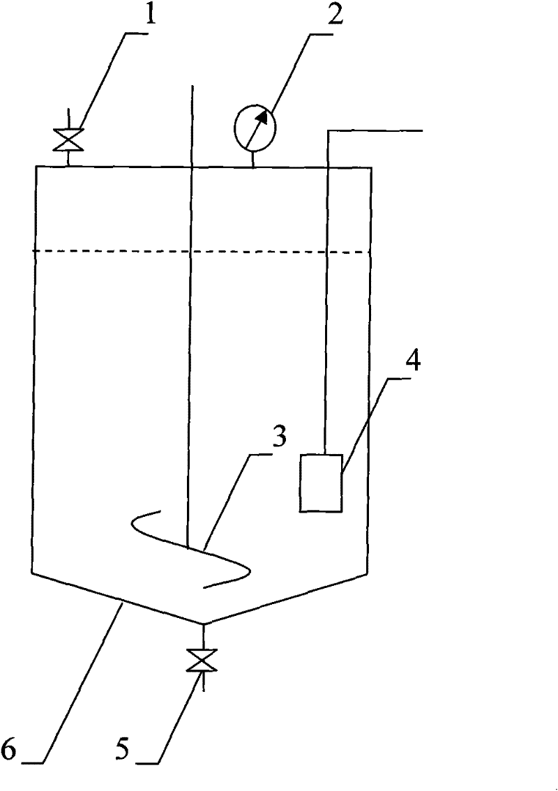
[0022] Design an ultrasonic defoaming device, the ultrasonic frequency of its ultrasonic generator 4 is designed to be 20kHz, and the ultrasonic power is designed to be 100W.

[0023] Use the above-mentioned defoaming device to prepare polysulfone hollow fibers by solution spinning: open the feed valve 1, and add materials such as polysulfone resin, solvent and additives with a total amount of 10 kg into the material-dissolving tank 6 according to the known process design, Close the feed valve 1; open the agitator 3 and the ultrasonic generator 4, and set the spinning temperature to the temperature of the spinning solution in the melting material tank 6; stir and simultaneously ultrasonically deaerate for 0.5h and then close the agitator 3, Continue defoaming for 5 minutes by ultrasonic waves until the bubbles in the solution completely disappear, and then turn off the ultrasonic generator 4 to obtain a completely defoamed and uniformly dissolved spinning solution. The resulti...

Embodiment 2

[0025] Design an ultrasonic defoaming device, the ultrasonic frequency of its ultrasonic generator 4 is designed to be 100kHz, and the ultrasonic power is designed to be 900W.

[0026] Use the above-mentioned defoaming device to prepare polyvinylidene fluoride hollow fibers by solution spinning: open the feed valve 1, and add materials such as polyvinylidene fluoride resin, solvent and additives with a total amount of 20kg to the solvent according to the known process design In the tank 6, close the feed valve 1; turn on the stirring 3 and the ultrasonic generator 4, and set the spinning temperature to the temperature of the spinning solution in the melting material tank 6; stir and at the same time ultrasonic degassing for 1 hour, then close the stirring 3 , using ultrasonic waves to continue defoaming for 15 minutes until the bubbles in the solution completely disappear, and then turn off the ultrasonic generator 4 to obtain a completely defoamed and uniformly dissolved spinn...

Embodiment 3

[0028] An ultrasonic defoaming device is designed, the ultrasonic frequency of the ultrasonic generator 4 is designed to be 200kHz, and the ultrasonic power is designed to be 5000W.

[0029] Use the above-mentioned defoaming device to prepare polyacrylonitrile hollow fibers by solution spinning: open the feed valve 1, and add materials such as polyacrylonitrile resin, solvent and additives with a total amount of 30kg into the material dissolving tank 6 according to the known process design In the process, close the feed valve 1; open the stirring 3 and the ultrasonic generator 4, and set the spinning temperature to the temperature of the spinning solution in the melting material tank 6; stir and simultaneously ultrasonic degassing for 3 hours and then close the stirring 3, use The ultrasonic wave continued to defoam for 30 minutes until the air bubbles in the solution completely disappeared, and then the ultrasonic generator 4 was turned off to obtain a completely defoamed and ...


PUM

PropertyMeasurementUnit
viscosityaaaaaaaaaa
viscosityaaaaaaaaaa
viscosityaaaaaaaaaa

Abstract

The invention discloses an embedded ultrasonic deaeration device and a deaeration process. The device mainly comprises a material dissolving tank with a temperature control system; the top of the material dissolving tank is provided with an inlet valve and a thermometer, while the bottom is provided with an outlet valve; and a stirrer externally connected with a transmission mechanism is arrangedin the material dissolving tank. The embedded ultrasonic deaeration device is characterized by also comprising an ultrasonic generator vertically arranged in the tank body of the material dissolving tank and directly contacted with spinning solution, wherein the ultrasonic generator has the ultrasonic frequency range of 20-200kHz and the ultrasonic power of 100-5,000W. The deaeration device is used in the deaeration process; and the deaeration process comprises the following steps of: adding spinning materials into the material dissolving tank according to the known process, starting the stirrer and the ultrasonic generator, setting the spinning temperature as the temperature of the spinning solution, stirring and performing ultrasonic deaeration for 0.5 to 3 hours; and after the materials are dissolved uniformly, closing the stirrer, continuously performing deaeration for 5 to 30 minutes by using ultrasonic waves until air bubbles completely disappear, and closing the ultrasonic generator.

Description

technical field [0001] The invention relates to a solution spinning technology, in particular to a built-in ultrasonic defoaming device and a defoaming process. The defoaming device and the defoaming process can be applied in the solution spinning process. Background technique [0002] In the commonly used chemical fiber spinning and forming process, solution spinning is an important method. During the solution spinning process, the defoaming effect of the spinning solution directly affects the quality of the product fiber, and the spinning solution with a small or even a small amount of air bubbles will damage or break the fiber at the bubble point, affecting the use. Conventional defoaming methods in the current spinning production have static defoaming, chemical drug defoaming and degassing under reduced pressure. It is conducive to continuous production; for spinning solutions with high viscosity, the defoaming effect is not ideal; (2) The chemicals added in the chemic...

Claims


Application Information

Patent Timeline
Patent Type & Authority Patents(China)
IPC IPC(8): D01D1/10
Inventor 王薇李新民刘建立刘玺张志超
Owner TIANJIN POLYTECHNIC UNIV
Why Eureka
Try Eureka