Small-angle well inclination state measuring method and device

A measurement method and technology of measurement device, which are applied in the directions of measurement, earthwork drilling, wellbore/well components, etc., can solve the problems of maximum uncertainty, interference and error, poor linearity, etc., to reduce nonlinear distortion, Accurate measurement results, avoiding the effect of signal flooding

Active Publication Date: 2014-01-22
XI'AN PETROLEUM UNIVERSITY
View PDF7 Cites 0 Cited by
  • Summary
  • Abstract
  • Description
  • Claims
  • Application Information

AI Technical Summary

Problems solved by technology

(4) Multi-degree-of-freedom combined measurement method; two sets of triaxial accelerometers are 30 meters apart, that is, three drill collars apart. Not only are the sensor groups on different drill collars difficult to install concentrically, but the long-distance small signal transmission has brought new problems. Interference and Error
(5) Non-linear correction method is adopted; correction and real-time signal processing are more complicated, and different corrections are required for locations with different latitudes and different magnetic field strengths
It can be seen that when the well deviation is small, the relative error varies in a large range, and the maximum value is also uncertain, resulting in poor linearity of measurement and greatly reduced accuracy

Method used


Image

  • Small-angle well inclination state measuring method and device
  • Small-angle well inclination state measuring method and device
  • Small-angle well inclination state measuring method and device

Examples


Embodiment 1

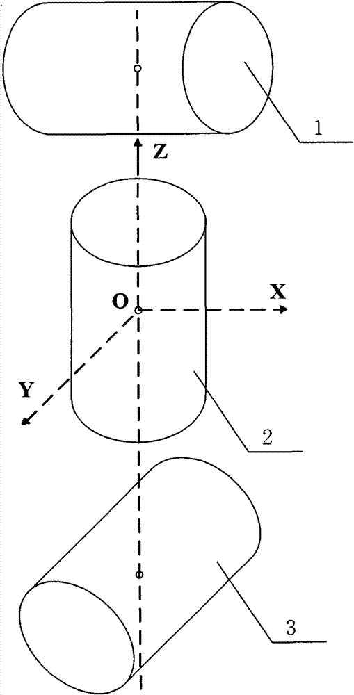
[0038] In this embodiment, first, take the spatial point O as the origin, take the line passing through point O and parallel to the X accelerometer as the X axis, take the direction passing through point O and parallel to the Y accelerometer as the Y axis, and take the line passing through point O And the direction parallel to the Z accelerometer is the Z axis, and a conventional orthogonal measuring instrument coordinate system OXYZ is established;

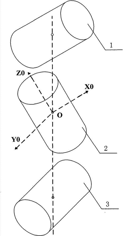
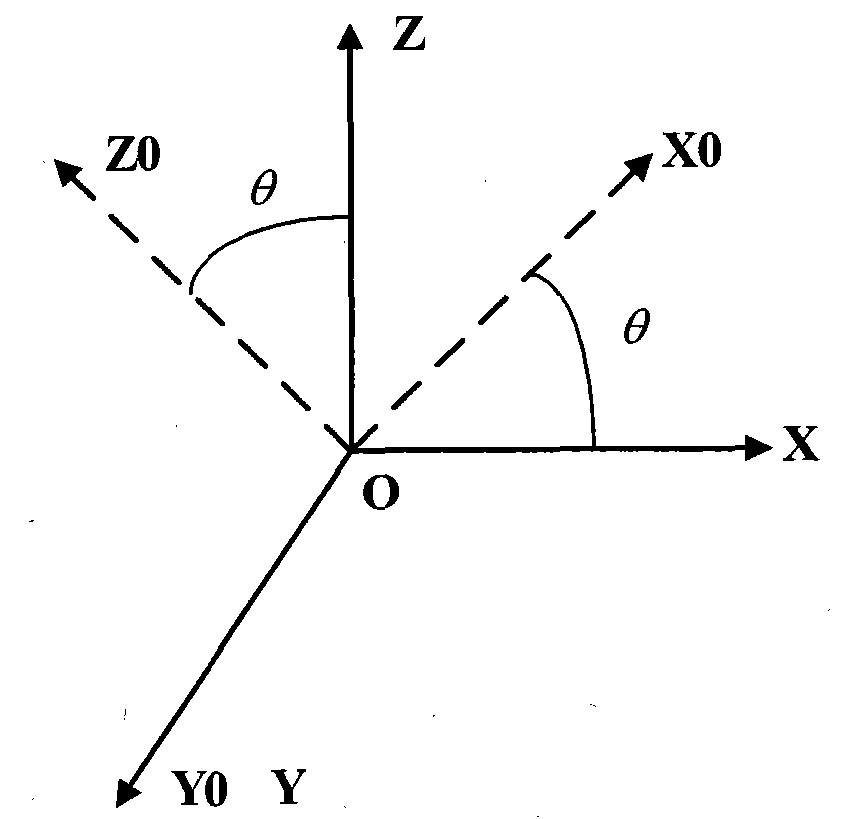
[0039] Then, the conventional measuring instrument coordinate system OXYZ is rotated 30° counterclockwise or clockwise around the Y axis to obtain a new measuring instrument coordinate system OX 1 Y 1 Z 1 , that is, the X accelerometer rotates 30° counterclockwise or clockwise around the Y axis, and the Z accelerometer also rotates 30° counterclockwise or clockwise around the Y axis, and the orientation of the Y accelerometer remains unchanged. The center of the detection element of the Z accelerometer is always on the same str...

Embodiment 2

[0044] In this embodiment, first, take the spatial point O as the origin, take the line passing through point O and parallel to the X accelerometer as the X axis, take the direction passing through point O and parallel to the Y accelerometer as the Y axis, and take the line passing through point O And the direction parallel to the Z accelerometer is the Z axis, and a conventional orthogonal measuring instrument coordinate system OXYZ is established;

[0045] Then, the conventional measuring instrument coordinate system OXYZ is rotated 45° counterclockwise or clockwise around the Y axis to obtain a new measuring instrument coordinate system OX 2 Y 2 Z 2 , that is, the X accelerometer rotates 45° counterclockwise or clockwise around the Y axis, and the Z accelerometer also rotates 45° counterclockwise or clockwise around the Y axis, and the orientation of the Y accelerometer remains unchanged. The X accelerometer, Y accelerometer and The center of the detection element of the ...

Embodiment 3

[0050] In this embodiment, first, take the spatial point O as the origin, take the line passing through point O and parallel to the X accelerometer as the X axis, take the direction passing through point O and parallel to the Y accelerometer as the Y axis, and take the line passing through point O And the direction parallel to the Z accelerometer is the Z axis, and a conventional orthogonal measuring instrument coordinate system OXYZ is established;

[0051] Then, the conventional measuring instrument coordinate system OXYZ is rotated 60° counterclockwise or clockwise around the Y axis to obtain a new measuring instrument coordinate system OX 3 Y 3 Z 3 , that is, the X accelerometer rotates 60° counterclockwise or clockwise around the Y axis, and the Z accelerometer also rotates 60° counterclockwise or clockwise around the Y axis, and the orientation of the Y accelerometer remains unchanged. The X accelerometer, Y accelerometer and The center of the detection element of the ...


PUM


Abstract

The invention discloses a small-angle well inclination state measuring method and a small-angle well inclination state measuring device. A conventional orthogonal measurement coordinate system OXYZ is rotated a theta angle around a Y axis to form a new measuring instrument coordinate system OX0Y0Z0, namely an X accelerometer is rotated a theta angle around the Y axis, a Z accelerometer is also rotated the theta angle around the Y axis, the X accelerometer is still orthogonal to the Z accelerometer, and the direction of a Y accelerometer is not changed; and according to values output by the accelerometers under the new measuring instrument coordinate system, values output by the accelerometers under the conventional orthogonal measurement coordinate system OXYZ are obtained through a coordinate transfer formula. A non-orthogonal coordinate system is adopted, so that a measuring sensor works in an area with the best linearity during vertical small-angle well inclination and has large output amplitude, signal submergence can be avoided, the nonlinear distortion of the sensor is reduced, the signal accuracy is improved, and an accurate small-angle well inclination state measuring result is obtained.

Description

technical field [0001] The invention is applied to petroleum engineering, belongs to the field of precision measuring instruments, and particularly relates to a method and a device for measuring the attitude of a small-angle well inclination. Background technique [0002] Vertical drilling is the main technology for oil exploration and development of deep and ultra-deep wells at home and abroad in the future, and the measurement of small-angle well inclination attitude is a key technology "bottleneck". According to the principle of downhole attitude measurement, the output of the attitude sensor is a trigonometric function of inclination angle, tool face angle and azimuth angle. When the vertical well inclination angle is small, the output signal of the sensor is very weak, and it is difficult to take into account the resolution and anti-interference performance at the same time. Require. The precise measurement of small-angle well inclination posture is the basic basis for...

Claims


Application Information

Patent Timeline
Patent Type & Authority Patents(China)
IPC IPC(8): E21B47/02
Inventor 程为彬汪跃龙汤楠霍爱清
Owner XI'AN PETROLEUM UNIVERSITY
Why Eureka
Try Eureka