Coreless cylindrical vibrating motor

A vibration motor, cylindrical technology, applied in electric components, control mechanical energy, electrical components, etc., can solve the problems of weakening vibration motor torque, shortening motor life, breakage, etc., to reduce current consumption, low current consumption, fast response characteristics Effect

Inactive Publication Date: 2011-06-29
WENDENG YONGBAI MICRO MOTOR CO LTD
View PDF6 Cites 1 Cited by
  • Summary
  • Abstract
  • Description
  • Claims
  • Application Information

AI Technical Summary

Problems solved by technology

Therefore, in order to make a vibration motor that requires low current consumption, the number of windings of the coil should be increased to increase the impedance, but the existing cylindrical vibration motor is limited (although the number of coils is increased by reducing the diameter of the enameled wire, reducing the wire diameter will weaken the vibration motor. Torque, the eccentric vibrator (10) has a problem with starting when it is heavy. On the contrary, if the weight of the vibrator (10) is reduced, although the start is easy, but the amount of vibration is reduced due to the weight reduction), the current consumption cannot be reduced because the commutator (25) when the motor rotates And electric brush (23) open and close electric shock to produce spark (arc) more, because produce spark (arc) a large amount of metal atoms of two pole parts are evaporated just produce electric corrosion and shorten the life-span of motor, in addition existing cylindrical vibrating motor is because of bearing The magnet (16) is installed on the outer periphery of the sleeve (15), so the limit of the magnet (16) needs to be increased, so the electromagnetic force must be increased, and it is difficult to improve the response speed. In addition, the cylindrical vibration motor installed in the mobile phone should be considered in the design The rotating part of the vibrator (10), because the end of the vibrator (10) installed on the rotating shaft is subjected to external impact, when a specific part is subjected to excessive external pressure, the rotating shaft (18) often bends or breaks.
[0009] With the expansion of the supply of touch-screen compatible smartphones that consume a lot of power, the current consumption, lifespan, and response speed of the vibration motor have become important factors. The amount of vibration required is limited by the inability to reduce the current consumption and increase the lifespan. Its structure cannot obtain a faster response speed because the volume of the magnet cannot be increased to increase the electromagnetic force. These existing cylindrical vibration motors have limitations and problems. It is the problem that the present invention needs to overcome

Method used


Image

  • Coreless cylindrical vibrating motor
  • Coreless cylindrical vibrating motor
  • Coreless cylindrical vibrating motor

Examples


Embodiment Construction

[0048] The desired example of the present invention is described in detail below with reference to the accompanying drawings:

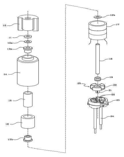
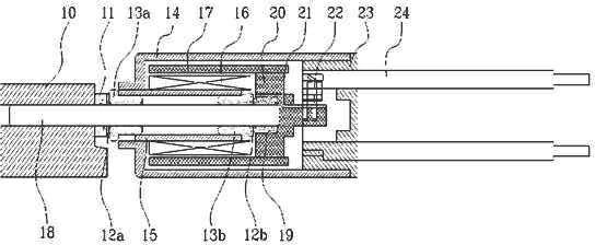
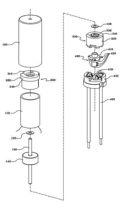
[0049] image 3 In order to decompose and demonstrate the constituent elements of the cylindrical vibration motor of the present invention, Figure 4 for assembly image 3 The internal sectional view of the cylindrical vibration motor of the constituent elements, Figure 5 In order to illustrate the cross-sectional view of the combination relationship between the vibration source on the upper part of the rotor and the coil applicable to the vibration motor of the present invention, Figure 6 In order to illustrate the brush terminal applicable to the vibration motor of the present invention and the plan view of the brush terminal for adjusting the brush fixed on the terminal, Figure 7 It is an explanatory diagram of the assembly method for installing a commutator in the lower vibration source suitable for the vibration motor of the present inventi...


PUM


Abstract

The invention relates to the technical field of vibrating motors, and more particularly relates to a coreless cylindrical vibrating motor which is arranged in a portable electronic device such as a mobile phone, a personal digital assistant (PDA) and the like and causes vibration when necessary. A rotor comprises a coil, first and second vibration sources and a commutator, wherein the coil is accommodated in a stator; the first and second vibration sources are separated from each other by a magnet and arranged oppositely, a center shaft is inserted in the first and second vibration sources, and the first and second vibration sources induce vibration when rotating eccentrically from the center shaft; and the commutator is fixed on the second vibration source and is run through by the center shaft. The rotor is arranged in a rotation space in a shell and can rotate; an electric brush is supported on an electric brush terminal, and is in electrical contact with a conductor commutator segment of the commutator; the electric brush terminal is pressed into one end which is fixed on the upper part of the open shell and is used for accommodating the center shaft for fixed supporting; and a vibrator is arranged in the shell but not outside the shell, so the length of the shell and the length of the coil arranged in the shell can be prolonged, and then low current consumption can be embodied, and the abrasion between the commutator and the electric brush can be reduced. Besides, the two vibration sources are combined with rotation in the coil, so the response speed can be improved, and high vibration force can be generated. The coreless cylindrical vibrating motor has the advantages of low current consumption, quick response, long service life, high vibrating force and the like.

Description

technical field [0001] The present invention relates to the technical field of vibrating motors, and more specifically is a hollow-cup cylindrical vibrating motor that is mounted on portable electronic devices such as mobile phones and PDAs to vibrate when necessary. Background technique [0002] As we all know, vibration motors are used to signal the incoming calls of mobile communication terminals such as mobile phones and PDAs. Recently, with the rapid increase of touch-screen mobile phones, the use of vibration motors has also changed. The performance of this multifunctional vibration motor needs to be different from that of existing vibration motors for the function and vibration function that feels realistic when playing games. It is required to be a high-performance vibration motor with fast response, high vibration force, low current consumption, and long life. [0003] figure 1 It is an exploded oblique view of the structure of the existing hollow cup cylindrical v...

Claims


Application Information

Patent Timeline
Patent Type & Authority Applications(China)
IPC IPC(8): H02K7/065
Inventor 李相宜
Owner WENDENG YONGBAI MICRO MOTOR CO LTD
Why Eureka
Try Eureka