Safe control time-base circuit

A time-based circuit and safety control technology, which is applied in the direction of electrical components, electronic switches, pulse technology, etc., can solve the problems of hidden dangers in use and failure to cut off the load power supply in time, so as to prevent loss of control, high cost performance, and improve safety performance effect

Inactive Publication Date: 2011-06-29
刘圣平
View PDF5 Cites 5 Cited by
  • Summary
  • Abstract
  • Description
  • Claims
  • Application Information

AI Technical Summary

Problems solved by technology

[0005] The invention mainly solves the technical problems that the original main control (over-limit control) circuit and timing circuit are often out of control due to abnormal faults, cannot cut off the load power supply in time, and has potential safety hazards; it provides a fault protection control function that can monitor In case of an abnormal fault, cut off the load power supply in time to ensure that the main control circuit does not go out of control, avoid serious accidents (such as fire), and ensure the use of a safe and safe control time base circuit

Method used


Image

  • Safe control time-base circuit
  • Safe control time-base circuit
  • Safe control time-base circuit

Examples


Embodiment 1

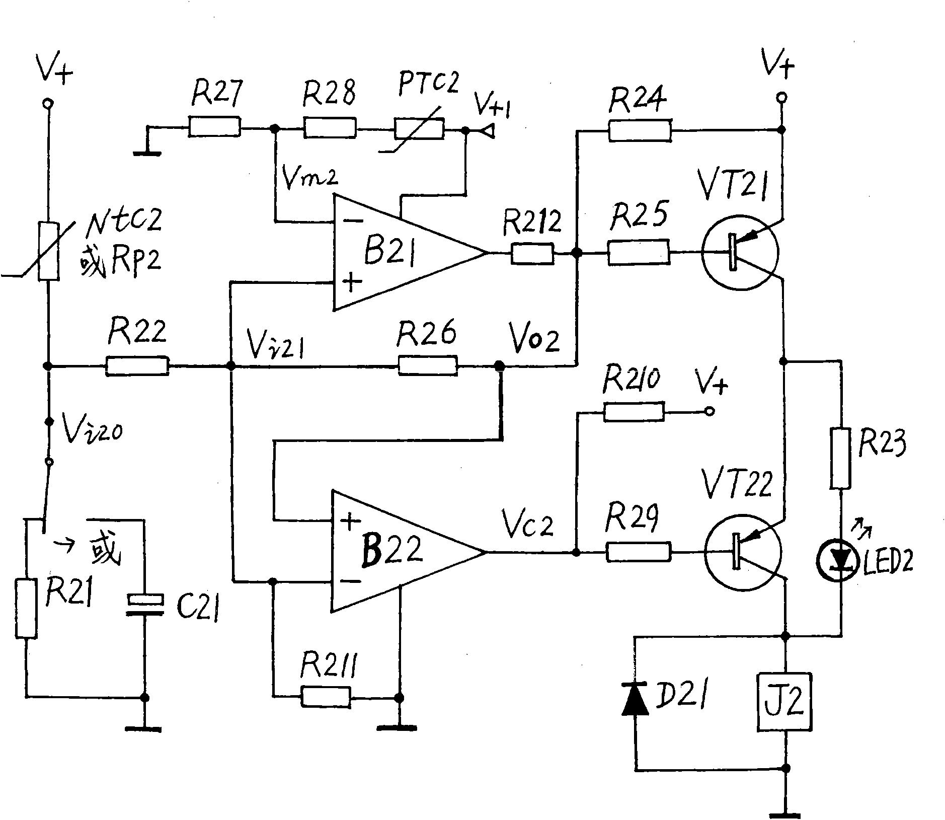
[0026] The specific circuit schematic diagram of this embodiment, as figure 2 As shown, the sensing circuit or integrating circuit (1) includes a thermistor NTC2 connected in series with a resistor R21, or a resistor Rp2 connected in series with a capacitor C21, and the bottom-matched main control circuit (6) includes an integrated operational amplifier or a voltage comparator B21 and a resistor R22, R26, R27, R28, thermistor PTC2, the protection and control circuit for bottom support and top protection (8) includes operational amplifier or voltage comparator B22, resistor R211, serial control push execution circuit and protection and control display circuit (9) includes triode VT21, VT22, resistors R23, R24, R25, R29, R210, relay J2, diode D21, light emitting diode LED2.

[0027] figure 2 Circuit connection mode: One end of the thermistor NTC2 is connected to the V+ pole of the power supply, the other end is connected to the resistor R21, and the other end of the resistor ...

Embodiment 2

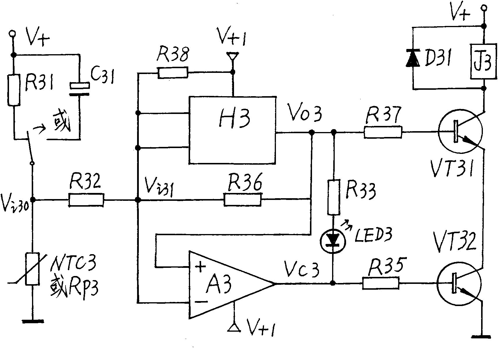
[0035] The specific circuit schematic diagram of this embodiment, as image 3 As shown, the sensing circuit or integrating circuit (1) includes a thermistor NTC3 connected in series with a resistor R31, or a resistor Rp3 connected in series with a capacitor C31. H3 and resistors R32 and R36, the bottom-supporting and top-protecting protection and control circuit (8) includes a voltage comparator or an operational amplifier A3, a resistor R38, the series control promotes the execution circuit and the protection and control display circuit (9) includes a triode VT31, VT32, and a diode D31 , Resistors R35, R37, relay J3, resistor R33, light emitting diode LED3.

[0036] image 3 Circuit connection mode: One end of thermistor NTC3 is grounded, the other end is connected to resistor R31, the other end of resistor R31 is connected to the V+ pole of the power supply, or one end of resistor Rp3 is grounded, the other end is connected to the negative pole of capacitor C31, and the pos...

Embodiment 3

[0044] The specific circuit schematic diagram of this embodiment, as Figure 4 As shown, the sensing circuit or integrating circuit (1) includes a thermistor NTC4 connected in series with a resistor R41, or a resistor RP4 connected in series with a capacitor C41. Buffer H4 and resistors R42 and R46, the bottom-supporting and top-protecting protection and control circuit (8) is an operational amplifier or voltage comparator B4 and resistor R48, and the serial control pushes the execution circuit and the protection and control display circuit to include triodes VT41, VT42, diode D41, Relay J4, resistors R43, R44, R45, R47, light-emitting diode LED4, a bottom-type main control circuit (6) and a top-supporting protection control circuit (8) are connected to the power supply V+1 terminal, and the sensing circuit or integral circuit ( 1) The serial control push execution circuit and the protection control display circuit (9) are connected to the V+ terminal of the power supply, and ...


PUM


Abstract

The invention belongs to a safe control time-base circuit guaranteeing the safety of an over-limitation control circuit or an timing control circuit in case of breakdown through preventing out-of-control, and the safe control time-base circuit is applied to temperature control electric apparatus, pressure control electric apparatus, water stage control electric apparatus and timing control electric apparatus, for improving the safety performance and avoiding serious accidents (fire, for example) during use. The following technical measure is taken for realizing the excellent function: most importantly, electronic devices are connected in a smart way to simply constitute a base-assembled master control circuit, a base-supported top-shielded protection and control circuit, a series-control propel executive circuit and a protection and control display circuit, wherein the base-assembled master control circuit and the base-supported top-shielded protection and control circuit are connected in parallel with signals output by a detection sensing circuit or a timing circuit. The protect loading of the base-supported top-shielded protection and control circuit monitors the control level output by the base-assembled master control circuit, so as to close the out-of-control level output by the master control circuit at first in case of breakdown and force the executive circuit to cut loading supply, thus the safety is guaranteed. Therefore, the safe control time-base circuit can be widely used in the field of electric application, and enables the electric apparatus to have high performance-price ratio.

Description

technical field [0001] The present invention relates to a control circuit / time base circuit, in particular to a safety control time base circuit that ensures that the main control (super upper and lower limit control) or the timing control circuit does not lose control when it fails, and is applied in temperature, pressure, water level, Timing control electrical appliances can improve safety performance and avoid serious accidents (such as fire) during use. Therefore, the present invention is more widely used in electronic application fields such as small household appliances and simple measurement, timing, control, safety protection, etc., and makes electrical products extremely cost-effective. Background technique [0002] In order to verify the novelty of the present invention, the designer consulted a large number of relevant technical materials (professional books, newspapers and periodicals), and retrieved relevant patent documents. It is only found that there are man...

Claims


Application Information

Patent Timeline
Patent Type & Authority Applications(China)
IPC IPC(8): H03K17/51
Inventor 刘圣平
Owner 刘圣平
Why Eureka
Try Eureka