Top-sealing and bottom safety control circuit and its safety temperature and time control electrical appliances

A technology of touch circuit and circuit, which is applied in the direction of program control, instrument and program control in the sequence/logic controller, which can solve the problems of the input terminal exceeding the bottom limit, out of control, and mutual short circuit failure of the ports, so as to avoid serious out of control Accidents, improved safety performance, cost-effective effects

Active Publication Date: 2019-01-04
刘圣平
View PDF9 Cites 0 Cited by
  • Summary
  • Abstract
  • Description
  • Claims
  • Application Information

AI Technical Summary

Problems solved by technology

[0005] The invention mainly solves the technical problems that the original basic main control (super upper and lower limit control and timing control) circuits are often out of control due to abnormal faults, cannot cut off the load power supply in time, and has potential safety hazards; it provides a core circuit module that can comprehensively monitor Input / output / setting / control / power supply ports have abnormal open-circuit faults and short-circuit faults adjacent to ports, or short-circuit faults between ports, or input terminals exceed the bottom limit, or the upper and lower limits are pushed to the top, etc., and cut off in time Load power supply to ensure that the main control circuit does not go out of control, avoid serious out-of-control accidents (such as fire or pressure explosion), and ensure the use of safe topping and bottoming safety control circuit HLT666 and its safety temperature and time control appliances

Method used


Image

  • Top-sealing and bottom safety control circuit and its safety temperature and time control electrical appliances
  • Top-sealing and bottom safety control circuit and its safety temperature and time control electrical appliances
  • Top-sealing and bottom safety control circuit and its safety temperature and time control electrical appliances

Examples


Embodiment 1

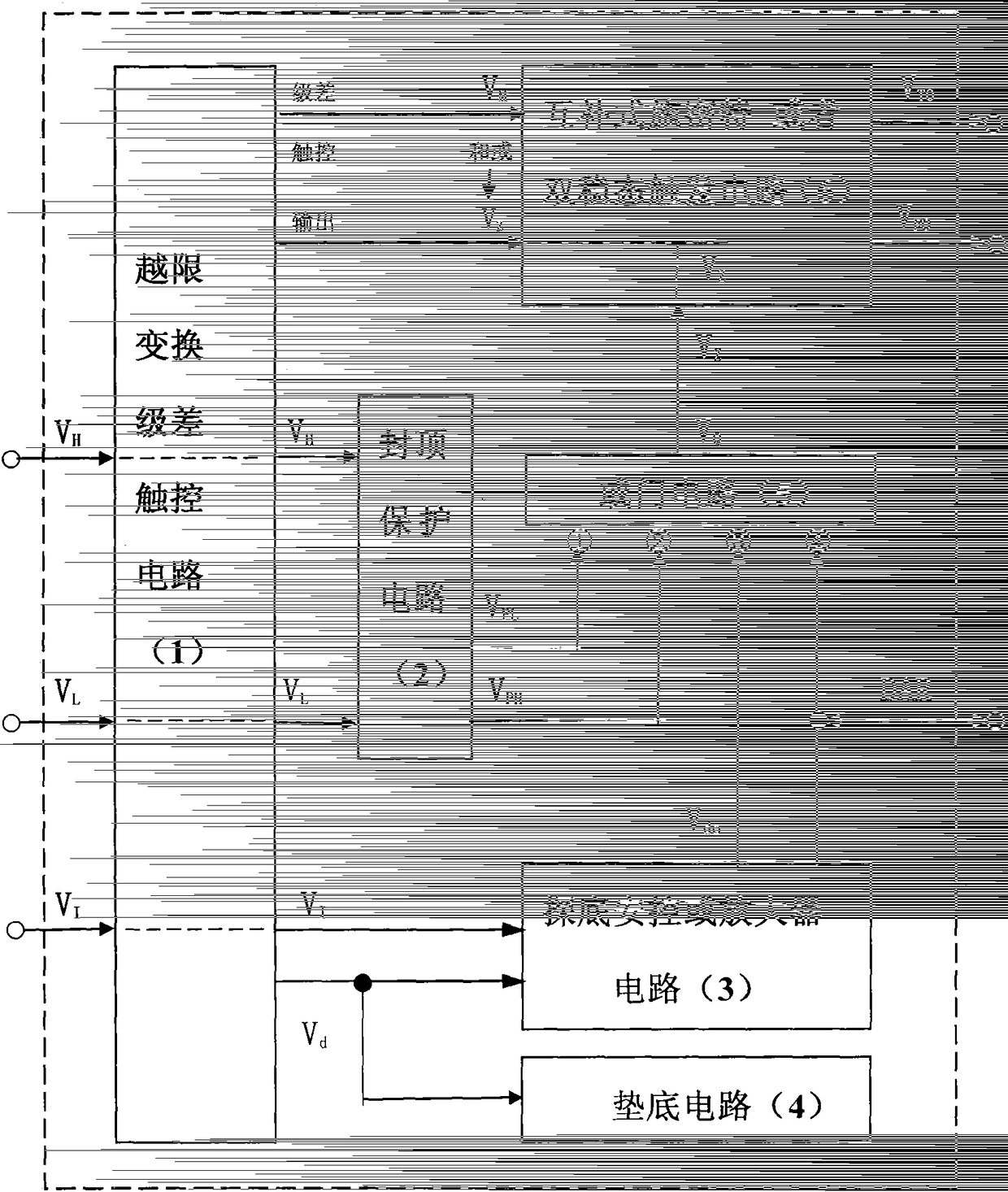
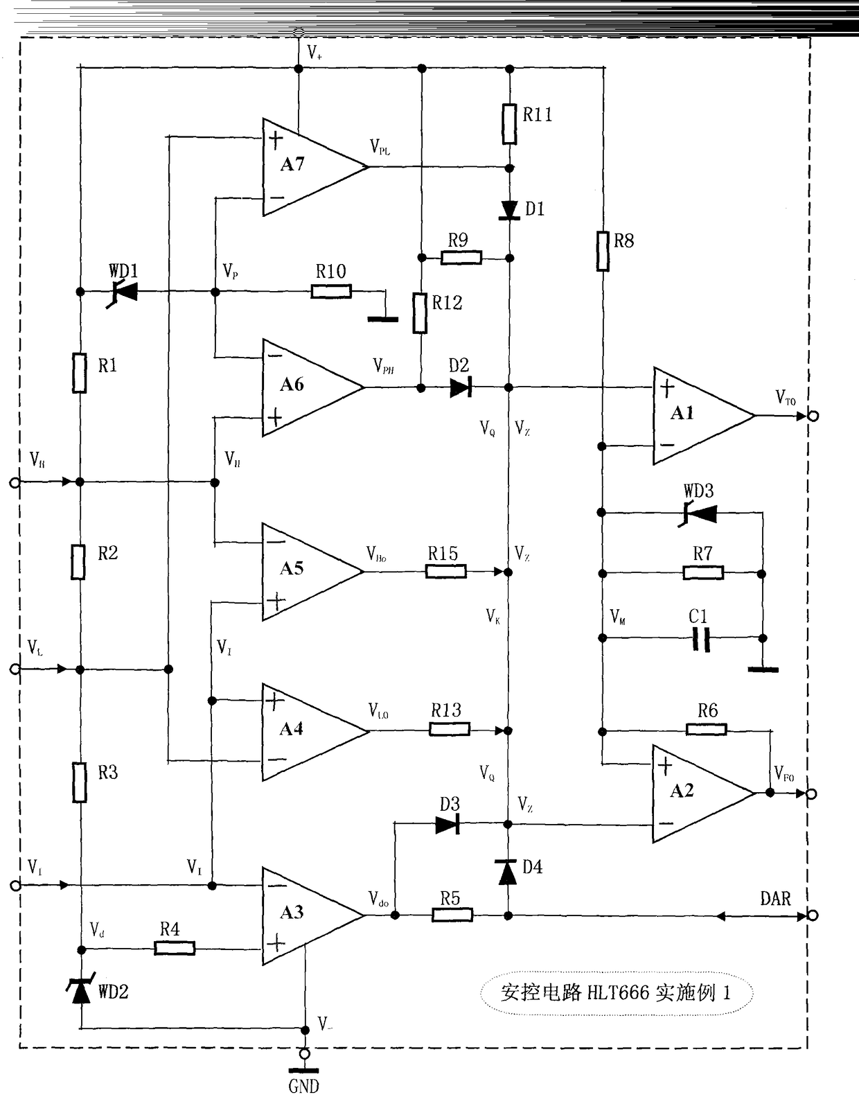
[0038] The specific circuit schematic diagram of embodiment 1, as figure 2 As shown, the over-limit conversion step difference touch circuit (1) includes operational amplifiers A4, A5, voltage dividing and limiting resistors R1, R2, R3 and conversion step difference resistors R9, R13, R15, and the capping protection circuit ( 2) include operational amplifiers A6, A7, Zener diodes WD1 and resistors R10, R11, R12, and the safety control or amplifier circuit (3) includes operational amplifiers A3 and resistors R4, R5, and the bottom circuit ( 4) comprise Zener diode WD2, described OR gate circuit (5) comprises diode D1, D2, D3, D4, described complementary bistable state or Schmitt trigger circuit (6) comprises operational amplifier A1, A2 and Zener diode WD3, resistors R6, R7, R8 and anti-interference capacitor C1; the resistor R2 is connected in series between resistors R1 and R3, the other end of resistor R3 is connected to the negative pole of Zener diode WD2, and the positiv...

Embodiment 2

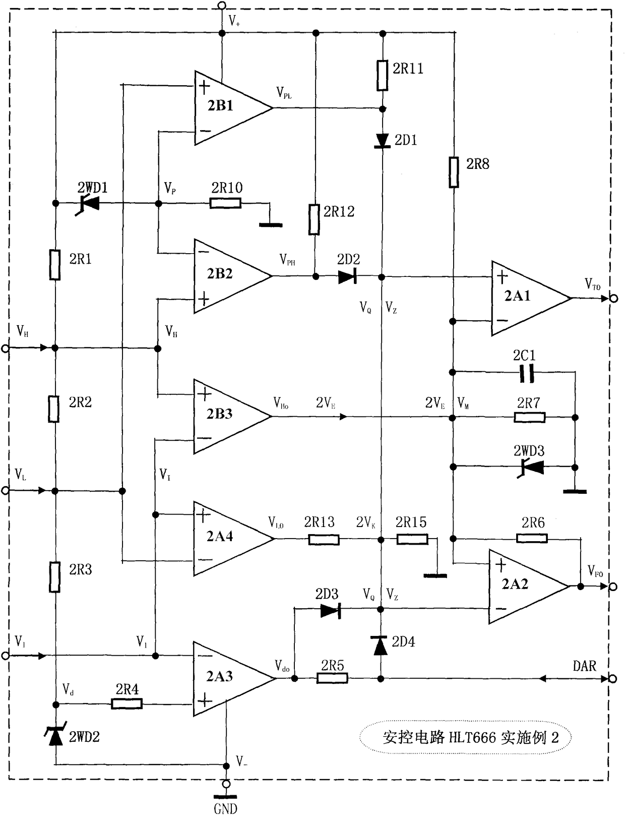
[0050] The specific circuit schematic diagram of embodiment 2, as image 3 As shown, the off-limit conversion step difference touch circuit (1) includes an operational amplifier 2A4, a voltage comparator 2B3, voltage dividing and limiting resistors 2R1, 2R2, 2R3 and conversion step difference resistors 2R13, 2R15, and the capping protection circuit (2) comprise voltage comparator 2B1, 2B2 and Zener diode 2WD1 and resistance 2R10, 2R11, 2R12, described safety control or amplifier circuit (3) comprise operational amplifier 2A3 and resistance 2R4, 2R5, described bottom Circuit (4) comprises Zener diode 2WD2, and described OR gate circuit (5) comprises diode 2D1, 2D2, 2D3, 2D4, and described complementary bistable state or Schmitt trigger circuit (6) comprises operational amplifier 2A1 , 2A2, Zener diode 2WD3, resistors 2R6, 2R7, 2R8 and anti-interference capacitor 2C1; the resistor 2R2 is connected in series between resistors 2R1 and 2R3, and the other end of resistor 2R3 is conn...

Embodiment 3

[0062] The specific circuit schematic diagram of embodiment 3, as Figure 4 As shown, the trans-limit conversion step difference touch circuit (1) includes voltage comparators 3B3, 3B4, voltage dividing and limiting resistors 3R1, 3R2, 3R3, conversion step difference resistors 3R9, 3R13, 3R15 and diode 3D5. The capping protection circuit (2) includes voltage comparators 3B1, 3B2, Zener diodes 3WD1 and resistors 3R10, 3R11, 3R12, and the bottom-out safety control or amplifier circuit (3) includes operational amplifiers 3A3 and resistors 3R4, 3R5. The bottom circuit (4) described above includes a Zener diode 3WD2, the OR circuit (5) includes diodes 3D1, 3D2, 3D3, 3D4, and the complementary bistable or Schmitt trigger circuit (6) includes Operational amplifiers 3A1, 3A2, Zener diode 3WD3, resistors 3R6, 3R7, 3R8 and anti-interference capacitor 3C1; the resistor 3R2 is connected in series between resistors 3R1 and 3R3, and the other end of resistor 3R3 is connected to the negative...


PUM


Abstract

The invention relates to a capping bottom safety control circuit and a safety temperature-control time-control electric appliance thereof. The technical scheme is that an out-of-limit conversion differential circuit is in parallel connected with two VH ends and two VL ends of a capping protection circuit, the out-of-limit conversion differential circuit is in parallel connected with the two input ends VI of a dip safety controller or an amplifier circuit, and the bottom limits of the out-of-limit conversion differential circuit and the dip safety controller of the amplifier circuit are set by a bottom circuit; the differential touch end of the out-of-limit conversion differential circuit is connected with an output end Vdo and a end DAR of the bottom safety controller or amplifier circuit, or the output end VQ of a gate circuit is connected with the end VZ of a Schmidt trigger circuit, and the output ends VTO and VFO of the Schmidt trigger circuit are externally connected with an execution circuit. The capping bottom safety control circuit provided by the invention can be applied to temperature, pressure, water level, timing and a measurement and control circuit, therefore the safety performance can be improved, the out of control accident can be prevented and the application is wide.

Description

technical field [0001] The invention relates to a control circuit, in particular to a "topping and bottoming safety control circuit and its safety temperature and time control electrical appliances" for general safety control, which can be used in temperature, pressure, water level, timing control and all limited measurement and control electrical appliances to improve safety. performance, to avoid serious out-of-control accidents such as fire or pressure explosion during use. Therefore, the present invention is widely used in electronic application fields such as small household appliances and simple limited measurement and control, timing control, safety protection, etc., and makes electrical products extremely cost-effective. Background technique [0002] In order to verify the novelty of the present invention, the inventor consulted a large amount of relevant technical materials (professional books, newspapers and periodicals), retrieved relevant patent documents, and on...

Claims


Application Information

Patent Timeline
Patent Type & Authority Patents(China)
IPC IPC(8): G05B19/04G05D23/20
CPCG05B19/0428G05B2219/2613G05D27/02
Inventor 刘圣平
Owner 刘圣平
Why Eureka
Try Eureka