Current and effect stabilizing control circuit chip and safe control electric appliance thereof

A control circuit chip, security control technology, applied in program control, computer control, general control system, etc., can solve problems such as loss of control, input terminal exceeding the bottom limit, hidden dangers in use, etc.

Pending Publication Date: 2015-09-30
刘圣平
View PDF0 Cites 6 Cited by
  • Summary
  • Abstract
  • Description
  • Claims
  • Application Information

AI Technical Summary

Problems solved by technology

[0003] The invention mainly solves the technical problems that the original basic main control (super upper and lower limit control and timing control) circuits are often out of control due to abnormal faults, cannot cut off the load power supply in time, and has potential safety hazards; it provides a core circuit module that can comprehensively monitor Input/output/setting/control/power supply ports have abnormal open-circuit faults and short-cir...

Method used


Image

  • Current and effect stabilizing control circuit chip and safe control electric appliance thereof
  • Current and effect stabilizing control circuit chip and safe control electric appliance thereof
  • Current and effect stabilizing control circuit chip and safe control electric appliance thereof

Examples


Embodiment 1

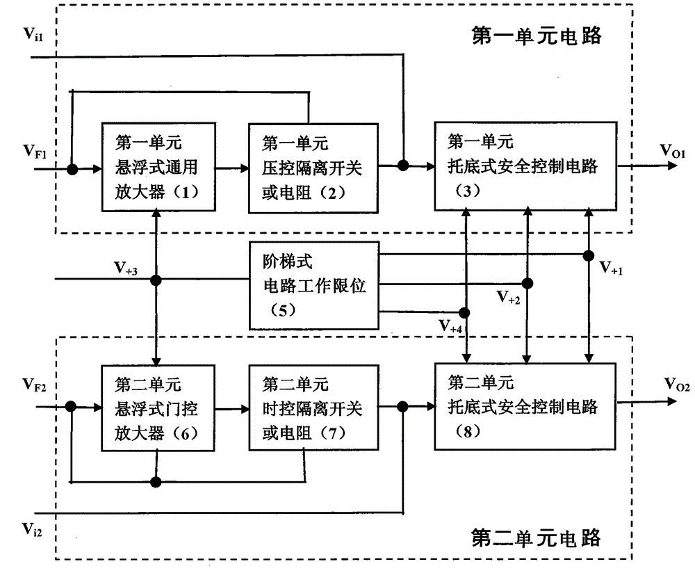
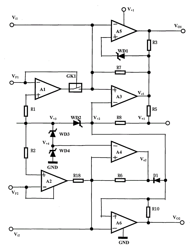
[0034] The specific circuit schematic diagram of embodiment 1, such as figure 2 As shown, the first unit floating universal amplifier (1) includes an operational amplifier A1 and a resistor R1, the first unit voltage-controlled isolation switch or resistor (2) includes a voltage-controlled isolation switch GK1, and the first unit The one-unit undercarriage safety control circuit (3) includes operational amplifiers A3, A5, Zener diode WD1 and resistors R3, R5, R7, and the second unit suspension gated amplifier (6) includes a gated operational amplifier A2 and resistor R2, the second unit time-controlled isolating switch or resistor (7) is replaced by resistor R8, the second unit bottom-type safety control circuit (8) includes operational amplifiers A4, A6 and diode D1 and Resistor R6, R10, the working limit of the ladder circuit (5) includes Zener diodes WD2, WD3, WD4 and resistor R8; the circuit connection mode is: the inverting (-) input terminal of the operational amplifier A...

Embodiment 2

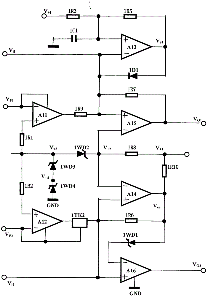
[0046] The specific circuit schematic diagram of embodiment 2, such as image 3 As shown, the combined circuit of the first unit floating universal amplifier (1) and the first unit voltage-controlled isolating switch or resistor (2) can be replaced with a floating gated amplifier circuit, including a gated operational amplifier A11 And resistors 1R1 and 1R9, the first unit undercarriage safety control circuit (3) includes operational amplifiers A13, A15, diode 1D1, capacitor 1C1 and resistors 1R3, 1R5, 1R7, and the second unit floating door The control amplifier (6) includes a gated operational amplifier A12 and a resistor 1R2, and the second unit time-controlled isolation switch or resistor (7) includes a time-controlled isolation switch 1TK2. If the time-control function is not required, the resistor can be used instead of the time-control Isolating switch 1TK2, the second unit support bottom type safety control circuit (8) includes operational amplifiers A14, A16, Zener diode...

Embodiment 3

[0058] The specific circuit schematic diagram of embodiment 3, such as Figure 4 As shown, the first unit floating universal amplifier (1) includes an operational amplifier A21 and a resistor 2R1, the first unit voltage-controlled isolation switch or resistor (2) includes a voltage-controlled isolation switch 2GK1, and the first unit The one-unit undercarriage safety control circuit (3) includes operational amplifiers A23, A25, diode 2D1 and resistors 2R3, 2R5, 2R7, and the second unit suspension gated amplifier (6) includes a gated operational amplifier A22, Resistor 2R1, the second unit time-controlled isolating switch or resistor (7) includes a time-controlled isolating switch 2TK2, and the second unit bottom type safety control circuit (8) includes voltage comparators B24, B26 and resistor 2R6 , 2R10, 2R12, the stepped circuit work limit (5) includes Zener diodes 2WD2, 2WD3, 2WD4 and resistor 2R8; the circuit connection mode is: the inverting (-) input terminal of the operat...


PUM


Abstract

The invention relates to a current and effect stabilizing control circuit chip and a safe control electric appliance of the control circuit chip. The current and effect stabilizing control circuit chip and the safe control electric appliance adopt the technical scheme that two parallel and complementary unit circuits are adopted for forming the current and effect stabilizing control circuit chip, wherein the input end of an isolation switch arranged in each unit circuit is connected with an amplifier; the output end of the isolation switch arranged in each unit circuit is connected with a bottom supporting type safe control circuit; weak sensing signals are amplified and are then transmitted to the bottom supporting type safe control circuit to be processed by the isolation switch; the strong sensing signals can be directly sent to the bottom supporting type safe control circuit to be processed directly from the level input end; each bottom supporting type safe control circuit has the bottom supporting protection and limit exceeding safety control function; in addition, the two bottom supporting type safe control circuits are mutually locked; if the inputs of the two unit circuits are used for parallelly detecting the sensing signals and the outputs of the two unit circuits are used for serially connecting a peripheral driving executing circuit, and the capability of comprehensively preventing the fault control loss is realized, so that when the current and effect stabilizing control circuit chip is applied to safety protection and test control circuits for the temperature, the pressure, the water level, the timing and the like, the safety performance can be improved, the control loss accident can be avoided, and the purposes are wide.

Description

Technical field [0001] The invention relates to a control circuit, in particular to a control circuit chip with a stable and stable effect and its safety control electrical appliances, which are used in temperature, pressure, water level, timing control and all limited-quantity measurement and control electrical appliances, which can improve safety performance and avoid use time Serious out-of-control accidents such as fire or pressure explosion occurred. Therefore, the present invention is widely used in electronic application fields such as small household appliances and simple limited measurement and control, timing control, safety protection, etc., and makes the electrical product performance / price ratio extremely high. Background technique [0002] In order to verify the novelty of the present invention, the inventor consulted a large number of related technical materials (professional books, newspapers and periodicals), and searched related patent documents, only to find th...

Claims


Application Information

Patent Timeline
IPC IPC(8): G05B19/048
CPCG05B19/048
Inventor 刘圣平
Owner 刘圣平
Why Eureka
Try Eureka