Magnetorheological damper with annular and disc-shaped liquid flow resistance channels simultaneously

A magnetorheological damper, disk-shaped technology, applied in the direction of vibration suppression adjustment, non-rotational vibration suppression, etc., can solve the problem of increasing the shear area of ​​the liquid flow resistance channel, small area of ​​the liquid flow resistance channel, and limited liquid flow damping force and other problems, to achieve the effect of simple structure, wide range of dynamic damping force and improved efficiency

Active Publication Date: 2011-07-13
CHONGQING UNIV
View PDF6 Cites 23 Cited by
  • Summary
  • Abstract
  • Description
  • Claims
  • Application Information

AI Technical Summary

Problems solved by technology

[0005] Aiming at the disadvantages of the magnetorheological damper in the prior art, such as the small flow resistance channel area, limited fluid flow damping force, and complex structure, the present invention proposes a magnetorheological damper without increasing the external size, coil winding, Under the premise of the excitation curr

Method used


Image

  • Magnetorheological damper with annular and disc-shaped liquid flow resistance channels simultaneously
  • Magnetorheological damper with annular and disc-shaped liquid flow resistance channels simultaneously
  • Magnetorheological damper with annular and disc-shaped liquid flow resistance channels simultaneously

Examples


Embodiment 1

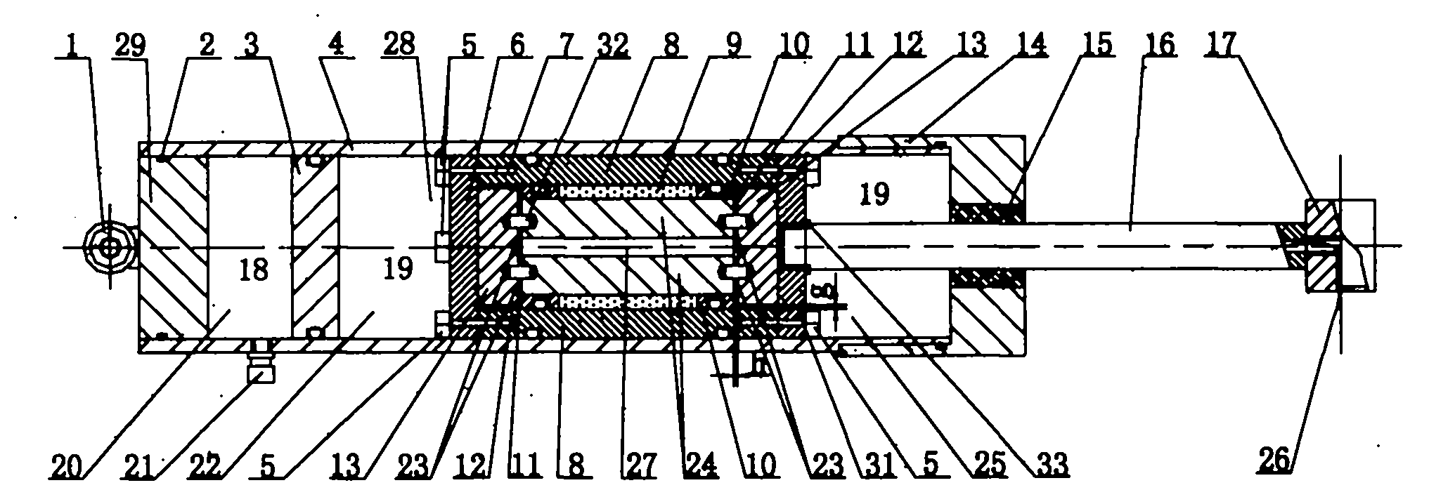
[0034] Embodiment one: see Figure 1-7 , the upper end cover 14 and the lower end cover 29 of the magneto-rheological damper with circular and disk-shaped liquid flow resistance channels are connected to the damper cylinder 4 through standard threads or non-detachable connection methods, and are sealed with O-shaped The ring 2 is sealed, and the piston head 28 is placed in the working medium magnetorheological fluid 19 . There is a transition fit between the floating piston 3 and the damper cylinder 4, and an O-ring is used for sliding sealing. The floating piston 3 isolates the inert gas 18 and the magneto-rheological fluid 19 in the compensation airbag 20 to realize the entry and exit of the piston rod 16 Air compensation at damper cylinder 4. The oil seal 15 is set in the upper end cover 14 and the piston rod 16 to complete the sealing of the internal magneto-rheological fluid 19. When the piston rod 16 enters and exits the damper cylinder 4, there will be no oil leakage. ...

Embodiment 2

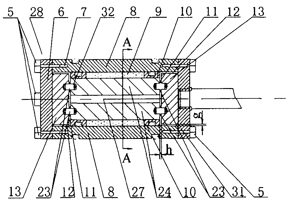
[0041] Embodiment two: with reference to attached Figure 8 and Figure 9 The structure in which the piston rod 16 reversely passes through the central hole 27 of the valve core in the piston head 28 to fix the piston head 28 is an extension of the structure of the present invention. with attached Figure 1-7 One difference of the illustrated embodiment is that the piston rod 16 has a reverse extension part opposite to the rod length direction, the diameter of the reverse extension part is smaller than the long part of the original rod and smaller than the diameter of the central hole 27 of the spool, The reverse extension part passes through the fixed disc 6 in the piston head 28, the connecting disc 31, the disc 13 and the valve core center hole 27, and stretches out from the other end face of the piston head 28, and its protruding part is provided with Thread, a nut with internal thread fits with the protruding part, the connection structure includes the reverse extension...

Embodiment 3

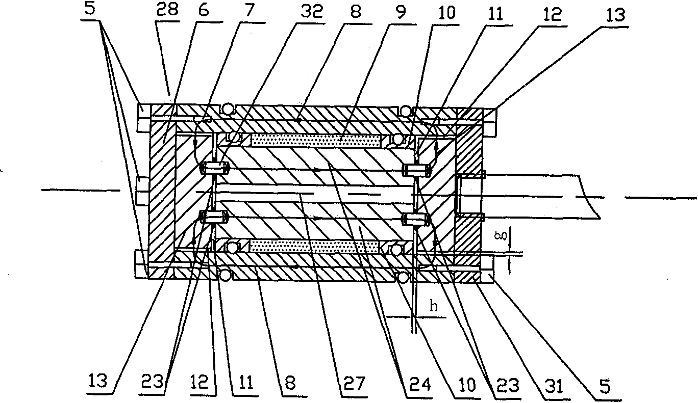
[0042] Embodiment three: with reference to attached Figure 10 and Figure 11 , is a diagram of a magneto-rheological damper with circular and disk-shaped fluid flow resistance channels while the magnetic circuit is closed by the magneto-rheological damper cylinder, which is another extended structure of the present invention. The spool 24 is in interference fit with the excitation coil former 10 that is wound with the excitation coil 9, and the attached Figure 8 and Figure 9Similarly, the spool 24 and the disc 13 are fixed together by the opposite extension of the piston rod 16 to form the piston head 28 . The excitation coil frame 10 on the piston head 28 and the damper cylinder 4 are transition fit, and the O-ring is used for sliding sealing. The discs 13 are arranged symmetrically outside the two ends of the spool 24 and are coaxial with the spool 24. The end faces of the discs 13 facing the spool 24 and the corresponding end faces of the spool 24 form a disc communic...


PUM


Abstract

The invention discloses a magnetorheological damper with annular and disc-shaped liquid flow resistance channels simultaneously, which comprises a damper cylinder body (4), a piston rod (16), a piston head (28), an upper end cover (14) and a lower end cover (29), wherein the piston head (28) comprises a magnet exciting coil (9), a magnet exciting coil rack (10), a valve core (24) with a longitudinal central through hole (27), a valve core outer cover (8), discs (13) symmetrically arranged outside the two end faces of the valve core (24), a disc-shaped liquid flow resistance channel (11) formed by the end face, which is opposite to the valve core (24), of the discs (13) and the end face corresponding to the valve core (24), and an annular liquid flow resistance channel (12) formed by the circumferential surfaces of the discs (13) and the inner circumferential surface of the valve core outer cover (8); the magnet exciting coil (9) and the valve core (24) belong to an internal magnetic circuit with a magnetic field; the magnetic field begins with the valve core (24), passes through the disc-shaped liquid flow resistance channel (11), the discs (13) and the annular liquid flow resistance channel (12), passes through the annular liquid flow resistance channel (12), the discs (13) and the disc-shaped liquid flow resistance channel (11) along the valve core outer cover (8) and is closed at the position of the valve core (24); and the valve core outer cover (8) can be disassembled from the piston head (28). The damper provided by the invention has the advantages of high efficiency, wide damping force dynamic range, simple structure, small volume and the like.

Description

technical field [0001] The present invention relates to a vibration control device, in particular to a magneto-rheological damper with circular and disk-shaped liquid flow resistance channels, which can be applied to bicycles, motorcycles, automobiles, trucks, ships, trains, Aircraft, bridges, buildings, sports facilities and other vibration control systems. Background technique [0002] The magnetorheological damper utilizes the rheological characteristics of magnetorheological fluid, and has the characteristics of large yield stress, fast response, low noise, low energy consumption, and stable and reliable operation. Its working principle is: a liquid flow resistance channel under the action of a magnetic field is set on the damper. When the piston of the magneto-rheological damper moves relative to the cylinder, the magneto-rheological fluid in the cylinder will be squeezed to make it Oriented movement in the flow resistance channel. When there is no magnetic field in t...

Claims


Application Information

Patent Timeline
IPC IPC(8): F16F9/53
Inventor 王代华白先旭
Owner CHONGQING UNIV
Why Eureka
Try Eureka