

Control method for auxiliary switching tube of active clamp flyback converter
A technology of auxiliary switch tube and flyback converter, which is applied in the conversion equipment with intermediate conversion to AC, control/regulation system, conversion of DC power input to DC power output, etc., can solve the problem of low efficiency and improve efficiency. , the effect of reducing no-load loss and switching loss
- Summary
- Abstract
- Description
- Claims
- Application Information
AI Technical Summary
Problems solved by technology
Method used
Image

Examples
Embodiment Construction
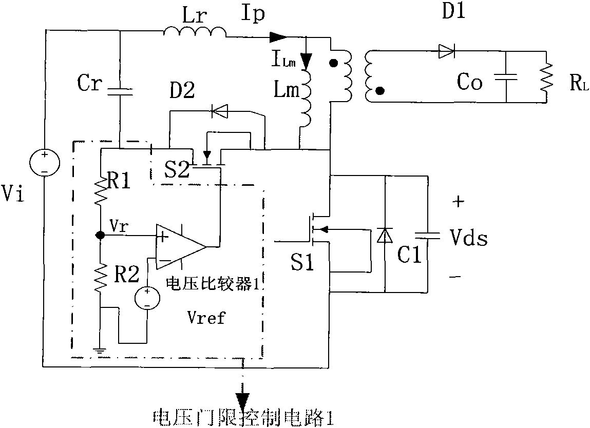
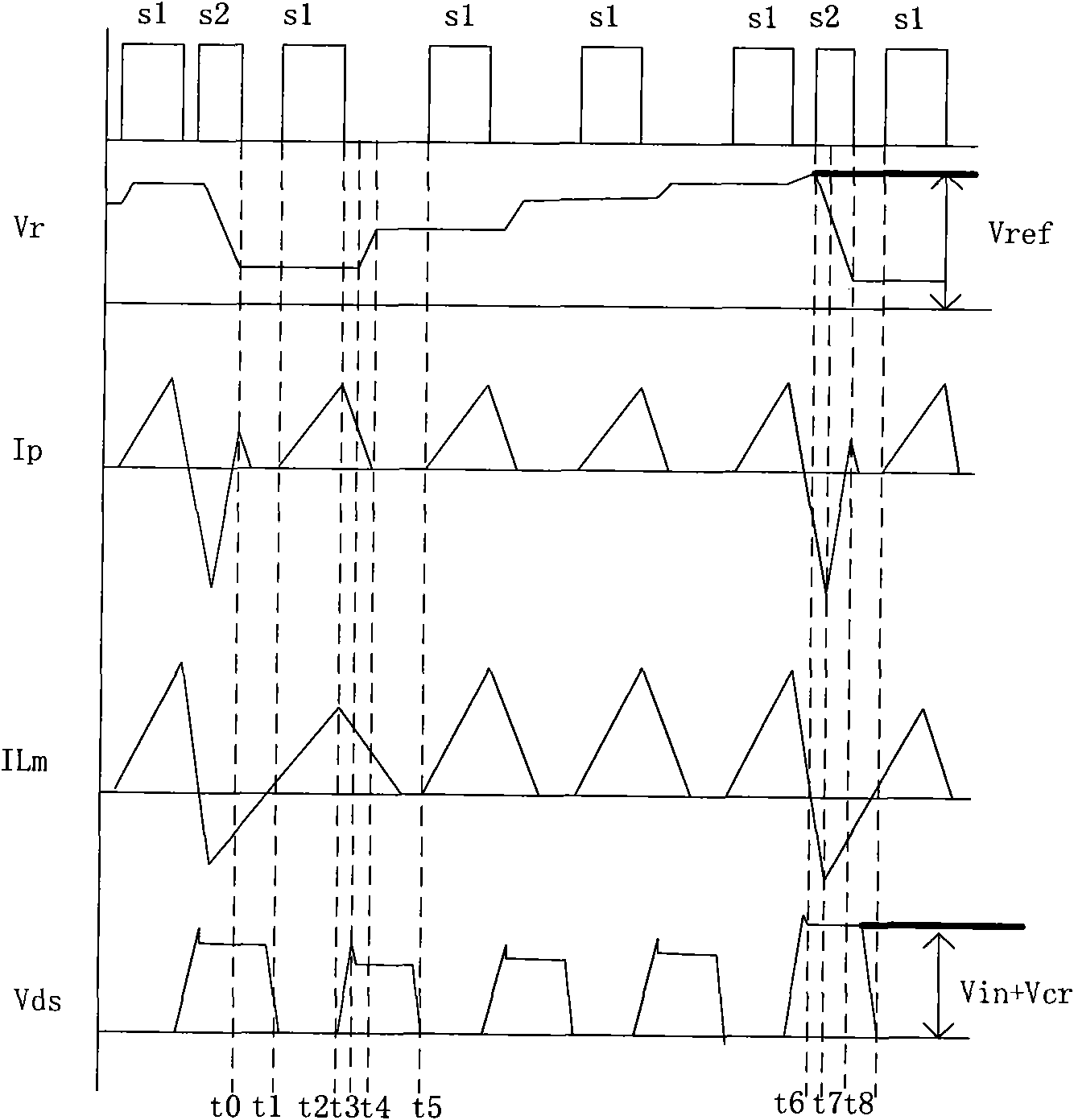
[0017] (1) combination image 3 , at time t0, the auxiliary switching tube S2 is turned off, and the primary side switching tube S1 and the auxiliary switching tube S2 are in the off state at the same time. t 1 At this time, the primary switching tube S1 is turned on, the primary current rises, the transformer stores energy, and the auxiliary switching tube S2 and the output rectifying diode D are turned off. The magnetizing inductance Lm and the leakage inductance Lr are linearly charged. The energy of the clamping capacitor Cr remains unchanged, and the voltage at both ends also remains unchanged.
[0018] (2)t 2 At this time, the primary switch S1 is turned on and turned off, and the resonant inductor current charges the parasitic capacitor C1 in a resonant manner. Due to the large excitation inductance Lm, the voltage Vds across the drain and source of the primary switch S1 rises approximately linearly.
[0019] (3)t 3 At this moment, Vds rises to Vi+Vc, and at this t...
PUM
 Abstract
Description
Claims
Application Information