Device for rapidly cutting off remote visible high-voltage test power supply

A high-voltage test and quick cut-off technology, which is applied to closed-circuit television systems, instruments, and alarms that rely on interference with short-wavelength radiation, can solve problems such as complicated personnel, misunderstandings, and poor communication quality, and eliminate potential safety hazards. Simple, reliable effects

Active Publication Date: 2011-07-13
JIAXING ELECTRIC POWER BUREAU +1
4 Cites 7 Cited by

AI-Extracted Technical Summary

Problems solved by technology

[0004] 2) It is often necessary to continuously apply high voltage to the test cable, the voltage is even as high as hundreds of thousands of volts, and the entire test time may be as long as 2 hours;
[0006] 4) Staff are required at the beginning and end of the cable test
[0011] The second is that the environment is complex and the personnel are numerous,
Therefore, "communication can only rely on words" leads to great security risks
[0016] 2) Poor communication quality, which can lead to misunderstanding
And only relying on the care of the terminal personnel cannot effectively gu...

Method used

The wireless transmission module that the present invention selects, is mainly concentrated in 136 ~ 174Mhz, 400 ~ 470Mhz and the radio frequency section for civil use on the market at present, all have no influence to protection, civil aviation, communication etc. In addition, the high frequency band has almost no influence on the equipment in the station. The 433Mhz wireless modules on the market are relatively mature. For this reason, the present embodiment selects RF905 wirele...

Abstract

The invention discloses a device for rapidly cutting off a remote visible high-voltage test power supply, and the device disclosed by the invention mainly comprises a safety control part, a remote visible part and a video/wireless signal transceiving part, wherein the safety control part is composed of a power supply control cabinet arranged at the head end of a cable and a warning sensor at the rear end of the cable; the remote visible part mainly comprises a video display unit at the head end of the cable and a video monitor at the rear end of the cable; the video/wireless signal transceiving part is respectively connected with the warning sensor and the video monitor, and receives and processes signals; and the video/wireless signal transceiving part is in remote connection with the power supply control cabinet through video-wireless and/or wireless radio-frequency signals. The device disclosed by the invention has the characteristics of simple structure, convenience in use, reliable performance, capability of eliminating certain potential safety hazards existing in the current cable tests better, and the like.

Application Domain

Technology Topic

Image

  • Device for rapidly cutting off remote visible high-voltage test power supply
  • Device for rapidly cutting off remote visible high-voltage test power supply

Examples

  • Experimental program(1)

Example Embodiment

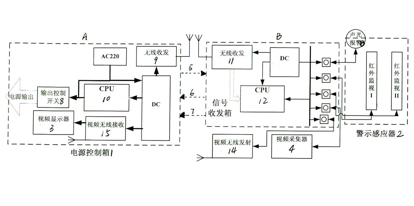
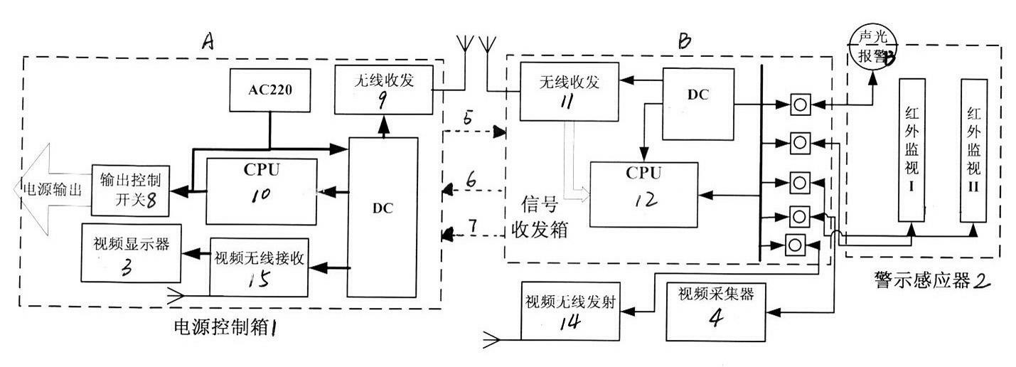
[0031] The present invention will be described in detail below in conjunction with the drawings: figure 1 As shown, the present invention mainly includes: a safety control part, a remote visual part and a video wireless signal transceiver part. The safety control part is composed of a power control box 1 at the cable head end A and a warning sensor 2 at the cable end B ; The remote visual part is mainly composed of the video display 3 (select TFT LCD) and the end video monitor 4 (select STARS Camera); the video/wireless signal transceiver part and the warning sensor 2 It is connected to the video monitor 4 and receives signals and processes. The video wireless signal transceiver part is connected to the power control box 1 remotely by video wireless and/or radio frequency signals; it includes the connection information 5, the transmission of dangerous information 6 and the video Wireless signal transmission 7.
[0032] The warning sensor 2 is composed of at least one set of infrared sensing devices. As shown in the figure, there are two sets of infrared sensing device I and infrared sensing device II. It connects the information by wireless transmission through the connected video wireless signal transceiver part. 5. Transmit dangerous information 6 and wirelessly connect with the power control box 1. The power control box 1 includes a CPU computer control module 10 and an output control switch 8 for controlling power output; connected to the CPU computer control module 10 There is a head-end wireless transceiver module 9, and the CPU computer control module 10 is also directly or indirectly connected to the video display 3.
[0033] figure 1 Also shown is: the head-end wireless transceiver module 9 is matched with the terminal wireless transceiver module 11 for wireless signal transceiver, and constitutes the wireless signal transceiver device of the video/wireless signal transceiver part, the terminal wireless The transceiver module 11 is connected to the warning sensor 2 through a CPU computer module 12; the CPU computer module 12 is also connected to an audible and visual alarm 13. RFC-33A is selected for the head-end wireless transceiver module 9 and the terminal wireless transceiver module 11; the CPU computer control module 10 and the CPU computer module 12 select ATmegall 6L-8AI.
[0034] The video/wireless signal transceiving part also includes a video wireless transmitting module 14 at the end and a video wireless receiving module 15 at the head end, the video wireless transmitting module 14 is directly or indirectly connected to the video monitor 4; The video wireless receiving module 15 is directly or indirectly connected to the video display 3. The video wireless transmitting module 14 and the video wireless receiving module 15 select the RTC6711 chip. The DC shown in the figure uses the PKK20-2 chip.
[0035] The infrared sensing device of the present invention can adopt a thermal sensor or a cutting sensor. Although the thermal sensor has a good circular range, the interference is too large, so the embodiment of the present invention adopts a cutting sensor.
[0036] The wireless transmission module selected by the present invention is currently used for civilian use in the market mainly in the 136~174Mhz, 400~470Mhz and radio frequency ranges, and has no impact on protection, civil aviation, communications, etc. In addition, the high frequency band has almost no effect on the equipment in the station. The wireless module of 433Mhz on the market is more mature. For this reason, the RF905 wireless module is selected in this embodiment to control its transmission power, which can achieve a wireless transmission distance within 2~3Km; the present invention also adopts the method of installing an antenna, expanding the gain and increasing the transmission power, thereby increasing the wireless transmission distance. For wireless video, the present invention uses the existing wireless module (REC6711) on the market.
[0037] The components shown in the figure are: power control box 1-receiving the dangerous cut-off signal and wireless video information wirelessly transmitted by the terminal signal transceiver box, where the dangerous signal acts to cut off the test power, and the video information is output to the video display. At the same time, it sends the power-on information to the signal transceiver box so that the latter will start the sound and light alarm.
[0038] Warning sensor 2——Receive the sound and light alarm control of the signal transceiver box; sense the intrusion of danger, and output the dangerous cut signal to the signal transceiver box.
[0039] Video monitor 4-Collect video information and output them to the signal transceiver box.
[0040] Video display 3—Receive the video signal from the power control box and output the display.
[0041] The signal transceiver box 16 is also called the terminal signal processing center. It receives the power on signal of the power control box and activates the sound and light alarm; it connects to the infrared induction dangerous cut off signal, and wirelessly transmits the cut off signal to the power control Box; access the video signal of the video monitor and transmit it to the power control box wirelessly.
[0042] The safety control part shown in the figure is mainly composed of a power control box 1 and a warning sensor 2.
[0043] 1) Power control box 1: Responsible for connecting and cutting off the test power. It consists of a power control module and a wireless radio frequency transceiver module. The control module turns on or off the power supply. The wireless radio frequency module and the radio frequency module in the cable end warning sensor carry out the wireless transmission and reception of information-when the power control box is connected to the test power supply, the radio frequency module sends the connection information to the end to activate the sound and light alarm; On the one hand, when it receives the dangerous information from the terminal, it activates the power control module to cut off the test power.
[0044] 2) Warning sensor 2: It consists of sound and light alarm and infrared sensor module. Among them, the sound and light alarm warns that the cable is live, and the signal transceiver box controls its disconnection. When the signal transceiver box receives the power-on signal from the head end, it will automatically start the sound and light alarm to alarm. The infrared sensor module is responsible for detecting illegal entry into the dangerous area of ​​the test. Once illegal entry is detected, it immediately inputs the dangerous cut-off information to the signal transceiver box, which wirelessly sends it to the power control box at the head end of the cable, which cuts off the test power.
[0045] The remote viewing part of the present invention is composed of a video monitor at the end and a video display at the head.
[0046] 1) Video monitor 4: Responsible for collecting terminal video information, and outputting the video information to the signal transceiver box, which is wirelessly transmitted to the head-end power control box.
[0047] 2) Video display 3: It consists of a display and a wireless receiver. It receives wireless video information from the terminal and processes this information for real-time display on the monitor.
[0048] The invention adopts modular and interface design, which is convenient to use. Use a power control box and a video display at the power application end, and use a warning sensor, a video monitor, and a signal transceiver box at the end.
[0049] 1) Use of power supply end (head end) devices-power control box, video display.
[0050] When applying power, the video crew can clearly see the end of the cable through the video display. After the power control box is connected to the power supply, it will immediately wirelessly send the connection information to the terminal signal transceiver box. And when it receives the dangerous cut-off signal at the end, it will cut off the power immediately.
[0051] 2) The use of the end (end) device of the power receiver-induction warning device, video monitor, signal transceiver box.
[0052] When the power control box is turned on, the signal transceiver box will receive the wireless connection information from it, and immediately activate the warning sensor sound and light alarm. At the same time, if the induction warning device senses a dangerous intrusion, it will input the cut-off signal to the signal transceiver box and transmit it wirelessly to the headend. In addition, the video monitor inputs the end situation to the signal transceiver box so that it can be sent wirelessly to the head end.
[0053] 3) When a person enters the scene of the dangerous area illegally, the sound and light alarm has stopped at this time, indicating that the head-end power supply has been cut off. At the same time, the head end video display really reflects the end situation.
[0054] The invention realizes the manual delay cut off from "ignoring" to "visible" and dangerous when the terminal is in danger to the rapid automatic cut off of sensing potential hazards, changing from passive to active, and greatly improving the safety of the test. At the same time, the applicable test distance is greater than 2km to meet the established target.
[0055] 1) Visual end at the head end
[0056] With this device, the head-end pressure personnel can see the end-site scene at a glance and can grasp the end-site scene well. Remote visibility has achieved a breakthrough from "zero" to "existence", greatly improving the safety of the test. On the other hand, Visible can better supervise the terminal staff to prevent their negligence, paralysis, etc.
[0057] 2) Unconditional and rapid cut-off of persons illegally entering the dangerous area
[0058] During the test, if a person at the end illegally enters the dangerous area and is sensed by the warning induction device, it will immediately wirelessly send the dangerous information to the head-end power control box, and the latter will quickly cut off the test power. The whole process only takes 1 second. Prevent problems before they happen, and improve the safety of the test.

PUM

no PUM

Description & Claims & Application Information

We can also present the details of the Description, Claims and Application information to help users get a comprehensive understanding of the technical details of the patent, such as background art, summary of invention, brief description of drawings, description of embodiments, and other original content. On the other hand, users can also determine the specific scope of protection of the technology through the list of claims; as well as understand the changes in the life cycle of the technology with the presentation of the patent timeline. Login to view more.

Similar technology patents

Method for composite skid proof treatment for nail and anchor, and treating structure

InactiveCN1916297AEliminate overall and local instability of loose rock and soil slopes and landslidesEliminate potential safety hazardsCoastlines protectionExcavationsRebarReinforced concrete
Owner:陈洪凯 +1

Nanometer boehmite and preparation method thereof

InactiveCN102815733AAvoid the use of strong acids and alkalisEliminate potential safety hazardsNanotechnologyAluminium oxides/hydroxidesIonBoehmite
Owner:TIANJIN BOYUAN NEW MATERIALS

Classification and recommendation of technical efficacy words

  • Simple structure
  • Eliminate potential safety hazards

Microlithographic projection exposure apparatus

InactiveUS20050068499A1Simple structureReliable and low-maintenance operationProjectorsPhotomechanical exposure apparatusCamera lensPhysics
Owner:CARL ZEISS SMT GMBH

Voice recognition method based on mobile terminal and mobile terminal

ActiveCN101840700AEnhanced sensing abilityEliminate potential safety hazardsVibration measurement in solidsSubstation speech amplifiersLoudnessEnvironmental sounds
Owner:YULONG COMPUTER TELECOMM SCI (SHENZHEN) CO LTD
Why Eureka
Try Eureka