Switchover method and terminal
A terminal and handover process technology, which is applied in the field of communication, can solve the problems of long handover interruption time, long occupation time, and affecting the normal business of the terminal, so as to eliminate the interruption time and improve the service experience.
- Summary
- Abstract
- Description
- Claims
- Application Information
AI Technical Summary
Problems solved by technology
Method used
Image

Examples
example 1
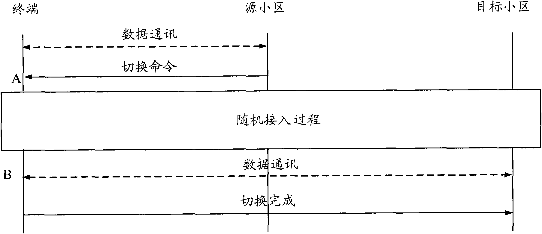
[0071] Figure 9 It is a schematic diagram of a preferred example 1 according to an embodiment of the present invention, such as Figure 9 As shown, cell 1 is an LTE cell, and the supported component carrier is CC1, which is located in frequency band 1. Cell 2 is an LTE cell and is an adjacent cell of Cell 1. The component carrier supported by Cell 2 is CC2, which is located in frequency band 1. The sending device and receiving device of the UE are a set of baseband devices, a single frequency band, the bandwidth is less than 20MHz, there is a first data communication module, plus a RACH module, which has its corresponding PHY layer. Cell 1 belongs to base station 1, and cell 2 belongs to base station 2.
[0072] Figure 10 It is a flow chart of preferred example 1 according to the embodiment of the present invention, combined below Figure 10 Describe the flow of this example.
[0073] Currently the UE is in a connected state in cell 1. The network side sends the measur...
example 2
[0081] Figure 11 It is a schematic diagram of the preferred example 2 according to the embodiment of the present invention, such as Figure 11 As shown, cell 1 is an LTE cell, and the supported component carrier is CC1, which is located in frequency band 1. Cell 2 is an LTE-A cell and is an adjacent cell of Cell 1. Cell 2 supports the aggregation of two component carriers, CC3 and CC4. These two component carriers are located in frequency band 1 and are continuous. The UE's sending device and receiving device are a set of baseband devices, a single frequency band, a bandwidth of 40MHz, a first data communication module, and an RACH module, which has its corresponding PHY layer. Cell 1 belongs to base station 1, and cell 2 belongs to base station 2.
[0082] Currently, the UE is in a connected state in cell 1, and the first data communication module is responsible for data communication with cell 1 on CC1. The network side issues the measurement task of the trigger event (A...
example 3
[0090] Figure 12 It is a schematic diagram of the third preferred example according to the embodiment of the present invention, as Figure 12 As shown, cell 1 is an LTE-A cell, and supports aggregation of two component carriers, CC1 and CC2, both of which are located in frequency band 1, and CC1 and CC2 are discontinuous. Cell 2 is an LTE-A cell and is an adjacent cell of Cell 1. Cell 2 supports the aggregation of three component carriers, CC3, CC4, and CC5. CC3 and CC4 are located in frequency band 2 and are discontinuous, and CC5 is located in frequency band 3. The sending device and the receiving device of the UE are three sets of baseband devices and three frequency bands, and the bandwidth of each frequency band is less than 20MHz, that is, the UE has three first data communication modules. Both cell 1 and cell 2 belong to base station 1 .
[0091] Figure 13 It is the flow chart of the preferred example 3 according to the embodiment of the present invention, combined...
PUM
 Abstract
Description
Claims
Application Information
 - R&D
- Intellectual Property
- Life Sciences
- Materials
- Tech Scout
- Unparalleled Data Quality
- Higher Quality Content
- 60% Fewer Hallucinations
Browse by: Latest US Patents, China's latest patents, Technical Efficacy Thesaurus, Application Domain, Technology Topic, Popular Technical Reports.
© 2025 PatSnap. All rights reserved.Legal|Privacy policy|Modern Slavery Act Transparency Statement|Sitemap|About US| Contact US: help@patsnap.com