Electronic lock

An electronic lock and circuit technology, applied in the field of electronic locks, can solve problems such as processing time, improve productivity, maintain waterproof performance, and shorten processing time.

Inactive Publication Date: 2011-07-13
PANASONIC CORP
View PDF2 Cites 3 Cited by
  • Summary
  • Abstract
  • Description
  • Claims
  • Application Information

AI Technical Summary

Problems solved by technology

[0012] However, in the conventional method, the step of causing the resin to reflow into the portion of the space 204 where the overpressure pin 205 exists, it is therefore necessary to draw out only the pressure pin 205 in the state where the first mold 201 and the second mold 202 are closed. The special molding machine, the processing take time, too
That is to say, the existing method has problems in the productivity of the electronic lock

Method used


Image

  • Electronic lock
  • Electronic lock
  • Electronic lock

Examples


Embodiment approach 1

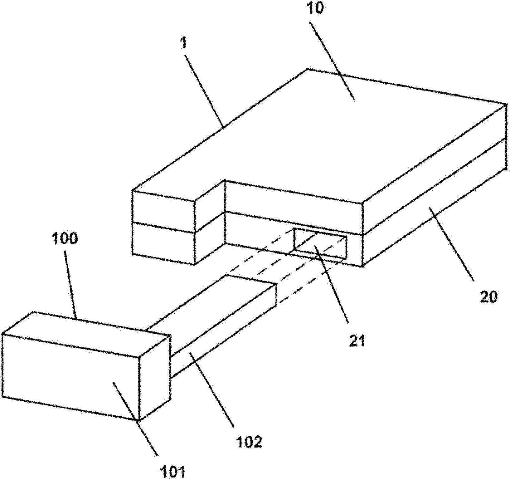
[0040] image 3 It is an exploded perspective view showing the portable device 1 of the electronic lock according to Embodiment 1 of the present invention. like image 3 As shown, the portable machine 1 includes an upper case 10 , a lower case 20 , an inner case 30 and a gasket 40 .

[0041] The upper case 10 is combined with the lower case 20 to house the inner case 30 and the gasket 40 inside. The lower housing 20 faces image 3 In the y-axis direction of , there is provided an insertion portion 21 capable of inserting the rod-shaped portion (equivalent to the rod-shaped portion 102 in FIG. 2 ) of the mechanical lock (equivalent to the mechanical lock 100 in FIG. 2 ) from the front end to the distal end. An opening 23 is provided at a distal end portion of the upper surface 22 of the insertion portion 21 . A rubber member 24 is fitted into the opening 23 to cover the opening 23 . In addition, the lower case 20 is provided with a concave portion 25 recessed from the uppe...

Embodiment approach 2

[0051] Embodiment 2 of the present invention will be described. The same symbols are assigned to the same parts as those in Embodiment 1 of the present invention, and description thereof will be omitted.

[0052] Figure 7 is an enlarged view around the rubber member 24 of Embodiment 2, which is the same as Figure 6 correspond. like Figure 7 As shown, on the upper surface 22 of the insertion portion 21 , at the periphery of the opening 23 , an edge portion 22 a protruding upward is formed. The rubber member 24 can be guided by this edge part 22a. Therefore, it is possible to more easily fit the rubber member 24 into the opening 23 provided on the upper surface 22 of the insertion portion 21 .


PUM


Abstract

Provided is an electronic lock which achieves improved productivity while maintaining the performance of waterproofness for an internal electronic circuit of an insertion portion for a mechanical lock. Specifically provided is an electronic lock provided with a portable machine (1) which contains an electric circuit that locks and / or unlocks a door by communicating with the outside wirelessly, and a mechanical lock which is attachable to and detachable from the portable machine (1) and mechanically locks and / or unlocks the door. In the electronic lock, the portable machine (1) comprises: an upper case (10) and a lower case (20) which house the electric circuit; an inner case (30) within the upper case (10) and lower case (20), in which the electric circuit is disposed; an insertion portion (21) within the lower case (20), into which the mechanical lock is insertable from the front end thereof and which has an opening (23) in the upper surface (22) at the terminal end thereof; and a rubber member (24) which is inserted into the opening (23) of the insertion portion (21).

Description

technical field [0001] The invention relates to an electronic lock with a mechanical lock for a remote control system for opening and closing doors. Background technique [0002] In recent years, remote control systems using electronic locks have been installed on vehicles. The remote control system performs wireless communication between a control unit mounted on a vehicle and an electronic lock carried by a user, and locks and / or unlocks doors of the vehicle in a non-contact manner. The electronic lock taken out of the car by the user is required to be waterproof and dustproof in order to prevent internal circuit failure. On the other hand, in order to cope with the emergency situation in which wireless communication cannot be carried out by the circuit inside the electronic lock, a mechanical lock (for example, referring to patent document 1). [0003] figure 1 It is a figure explaining the conventional electronic lock provided with the mechanical lock. like figure ...

Claims


Application Information

Patent Timeline
Patent Type & Authority Applications(China)
IPC IPC(8): E05B19/00
CPCE05B19/0082G07C2009/00984E05B19/046G07C9/00944Y10T70/7831Y10T70/7876Y10T70/8676
Inventor 佐佐木康一
Owner PANASONIC CORP
Why Eureka
Try Eureka