Electronic screw press

An electric screw and press technology, applied in the field of forging machinery, can solve the problems of wasting energy, easily damaged forging molds, and difficult to control the impact force, etc., and achieve the effects of long service life, good lubrication conditions, and low friction loss

Inactive Publication Date: 2011-07-20
王一多 +1
View PDF6 Cites 6 Cited by
  • Summary
  • Abstract
  • Description
  • Claims
  • Application Information

AI Technical Summary

Problems solved by technology

In addition, there is another kind of friction screw press. The motor reducer drives the friction plate to drive the flywheel to rotate to achieve energy strike. This kind of friction screw press is not only difficult to control the strike force, the forging mold is easily damaged, and wastes energy. There are tens of thousands of units in use in the world, whether to eliminate or transform is a topic that needs to be studied at present

Method used


Image

  • Electronic screw press
  • Electronic screw press
  • Electronic screw press

Examples


Embodiment Construction

[0023] The present invention is described in detail below in conjunction with accompanying drawing:

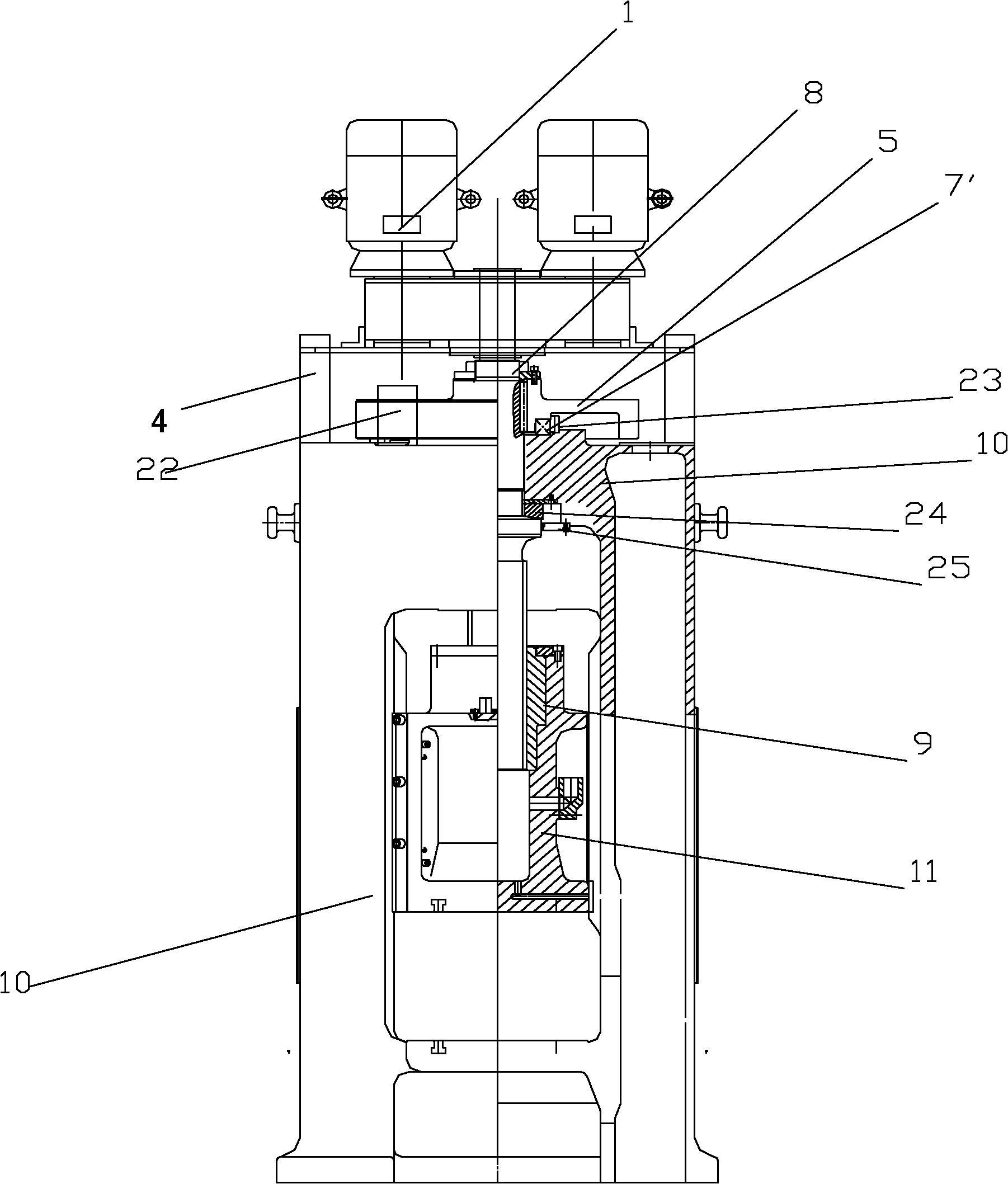
[0024] Such as Image 6 As shown, the structure of the present invention is used for the transformation of the old-fashioned friction press: the friction disc 34, the large pulley 28, the small pulley 30, the belt 29, the bracket 32, the motor 31, the connecting shaft 33, the bearing seat 35 of the old-fashioned friction press All dismantled, reformed cost invention, just has the characteristic of electric screw press.

[0025] The brake device, the displacement measuring device and the micro-control electrical system of the present invention are all existing devices, which are purchased directly from the market.

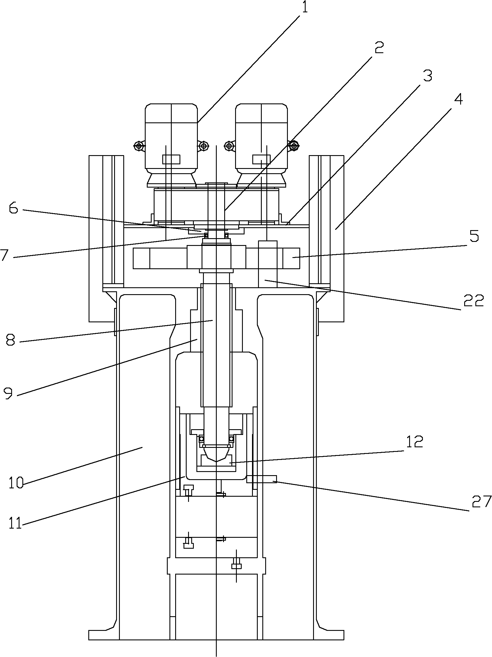
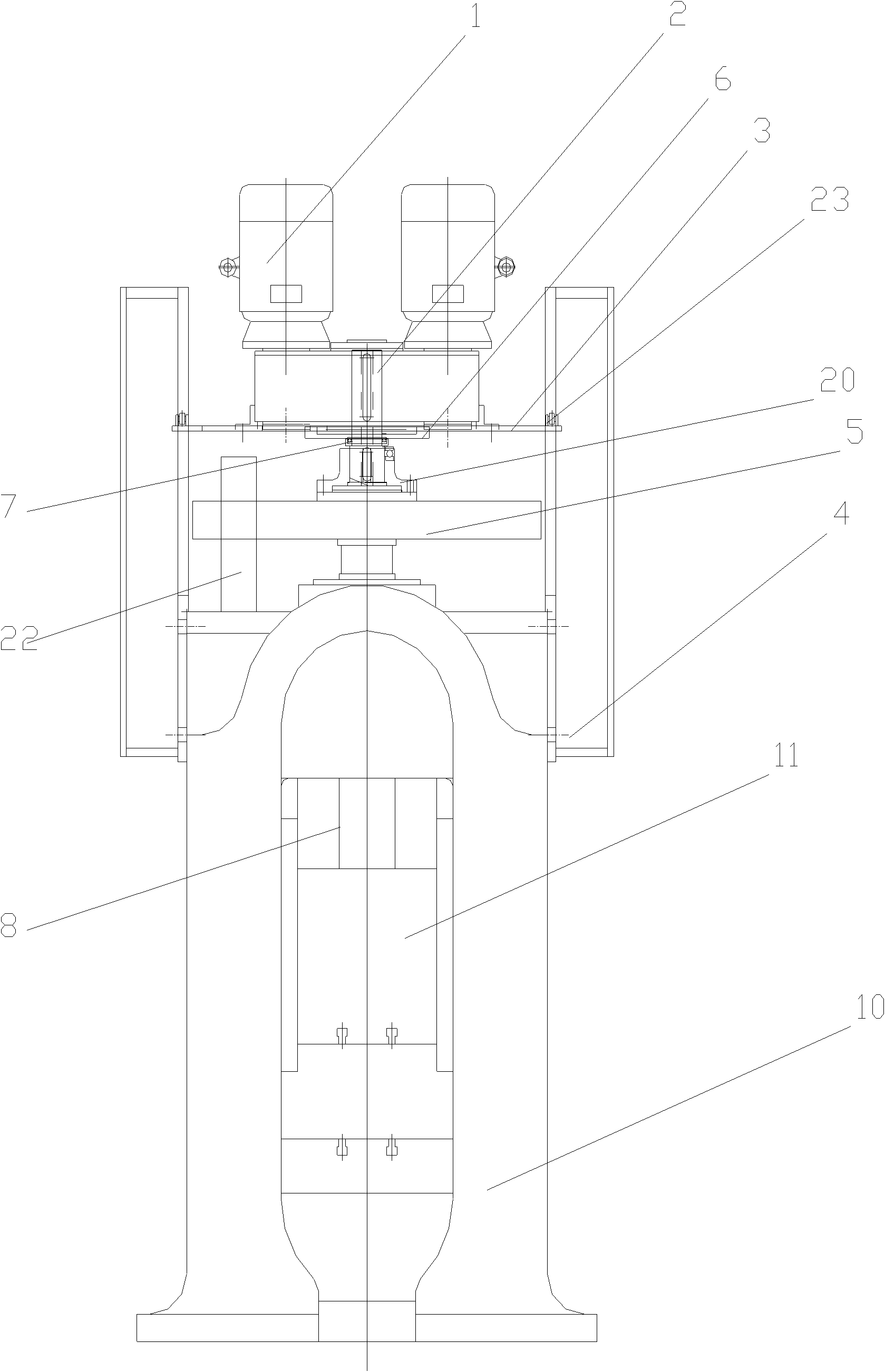
[0026] Such as figure 1 As shown, the present invention includes: an electric screw press, including: a motor reducer 1, a shaft 2, a torque limiting arm 3, a chute 4, a flywheel 5, a tray 6, a bearing 7, a screw 8, a nut 9, a bed 10. Slider 11, braking device 22...


PUM


Abstract

The invention relates to an electronic screw press. For the structure of the electronic screw press, a nut is arranged at the upper end of a lathe bed or a slide block; the slide block is arranged in the middle of the lathe bed; a screw rod is matched with and passes through the nut; the upper end of the screw rod is tightly connected with a flywheel; a shaft is arranged at the upper end of the screw rod; a torque control arm / torque control rod is arranged on the body of a motor speed reducer; the output part of the motor speed reducer is matched and connected with the screw rod through the shaft to form a whole; at least one end of the torque control arm / torque control rod is inserted into a sliding way / sliding post on the lathe bed; the lower end of the screw rod is arranged in the slide block; a brake device is arranged above the lathe bed; and a micro-control appliance system controls the running process of the press. The motor speed reducer is directly connected, and thus is convenient for assembly and maintenance; a gear is arranged in a tank body, and thus has good lubricating condition and high transmission efficiency; and the radial stress between the screw rod and the nut is small, so the abrasion loss is low, the service life is long, the blow energy is controllable, the safety coefficient is high, and energy is saved.

Description

technical field [0001] The invention relates to a forging machine, in particular to a screw press. Background technique [0002] There are many types of traditional electric screw presses, and there are two main types at present. One is to use a low-speed high-torque motor, which is directly installed on the top of the main machine. The rotor of the motor is a part of the flywheel. The motor must be specially manufactured. When the motor fails, maintenance is more difficult. The other is that the motor reducer is installed on the fuselage, the head of the motor is equipped with a small gear, and the top of the screw is equipped with a large gear (that is, a flywheel) to cooperate with it. The pinion of the gear transmission of this structure needs to be specially manufactured. , and the transmission power loss is large, easy to damage, and the installation of the motor reducer is inconvenient. At present, most of the electric screw presses have their nuts installed in the ...

Claims


Application Information

Patent Timeline
IPC IPC(8): B30B1/18B21J9/18
Inventor 王一多陈柏金邬凡
Owner 王一多
Why Eureka
Try Eureka