System for lifting and sliding large-tonnage steel box girder in land area and shoal area and construction method thereof

A technology of steel box girder and large tonnage is applied in the field of lifting slip system, which can solve the problems of long construction period, low construction efficiency, high cost and high cost, and achieve the effect of shortening construction period, realizing lifting and installation, and improving work efficiency.

Active Publication Date: 2011-07-20
THE 2ND ENG CO LTD MBEC +1
View PDF3 Cites 25 Cited by
  • Summary
  • Abstract
  • Description
  • Claims
  • Application Information

AI Technical Summary

Problems solved by technology

[0002] In the existing bridge construction, large-tonnage steel box girders are usually manufactured in factories, transported to the construction site by waterway, and then lifted and installed by a large floating crane. This method usually has high requirements on the navigable water level at the construction bridge site. And it takes a long time to occupy the waterway, and at the same time, it is limited by the water level of the waterway, which requires high environmental conditions at the construction site, long construction period, low construction efficiency, high cost, and low promotion.

Method used


Image

  • System for lifting and sliding large-tonnage steel box girder in land area and shoal area and construction method thereof
  • System for lifting and sliding large-tonnage steel box girder in land area and shoal area and construction method thereof
  • System for lifting and sliding large-tonnage steel box girder in land area and shoal area and construction method thereof

Examples


Embodiment Construction

[0023] The present invention will be further described below with reference to the accompanying drawings and specific embodiments, so that those skilled in the art can better understand and implement the present invention, but the examples cited are not intended to limit the present invention.

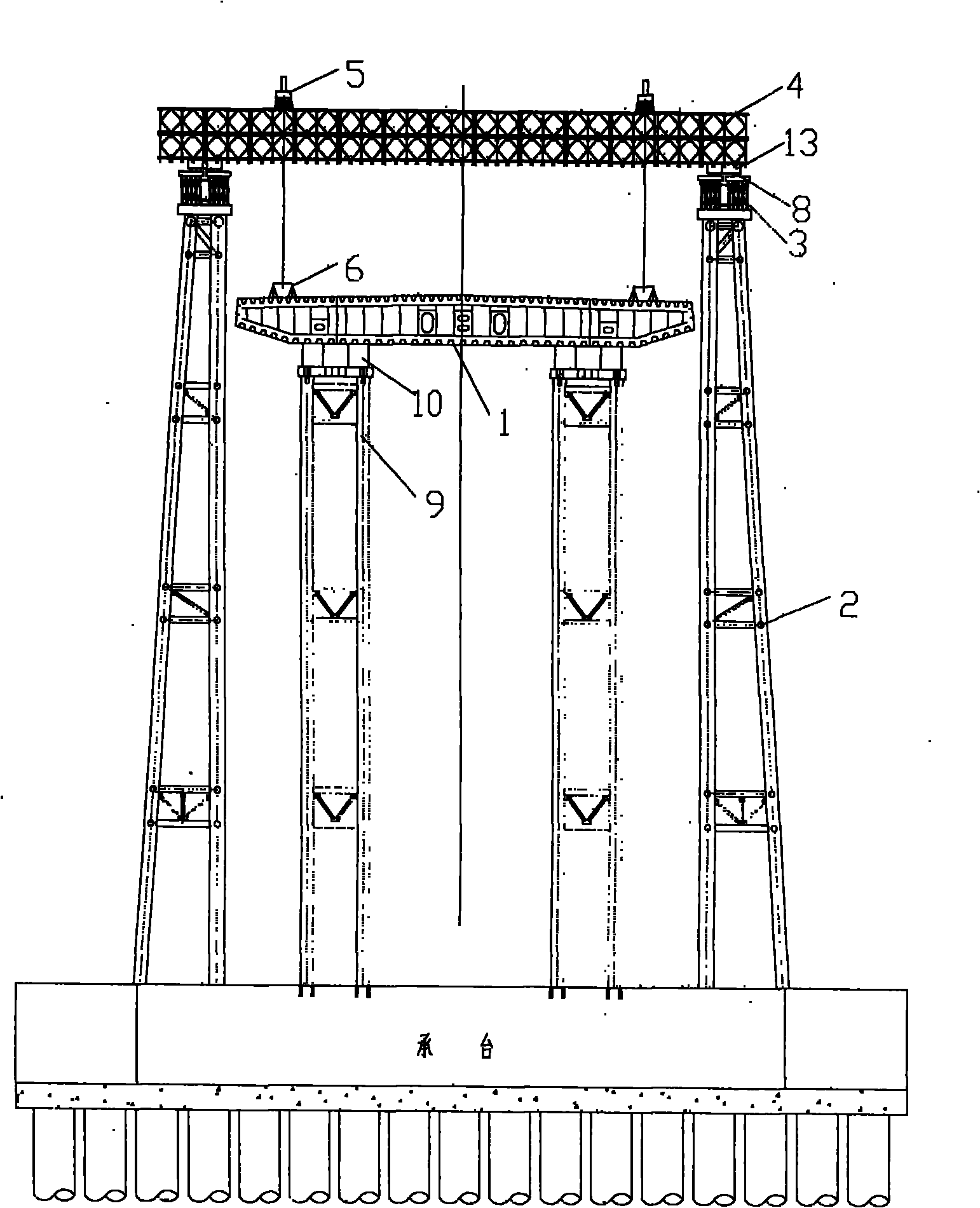
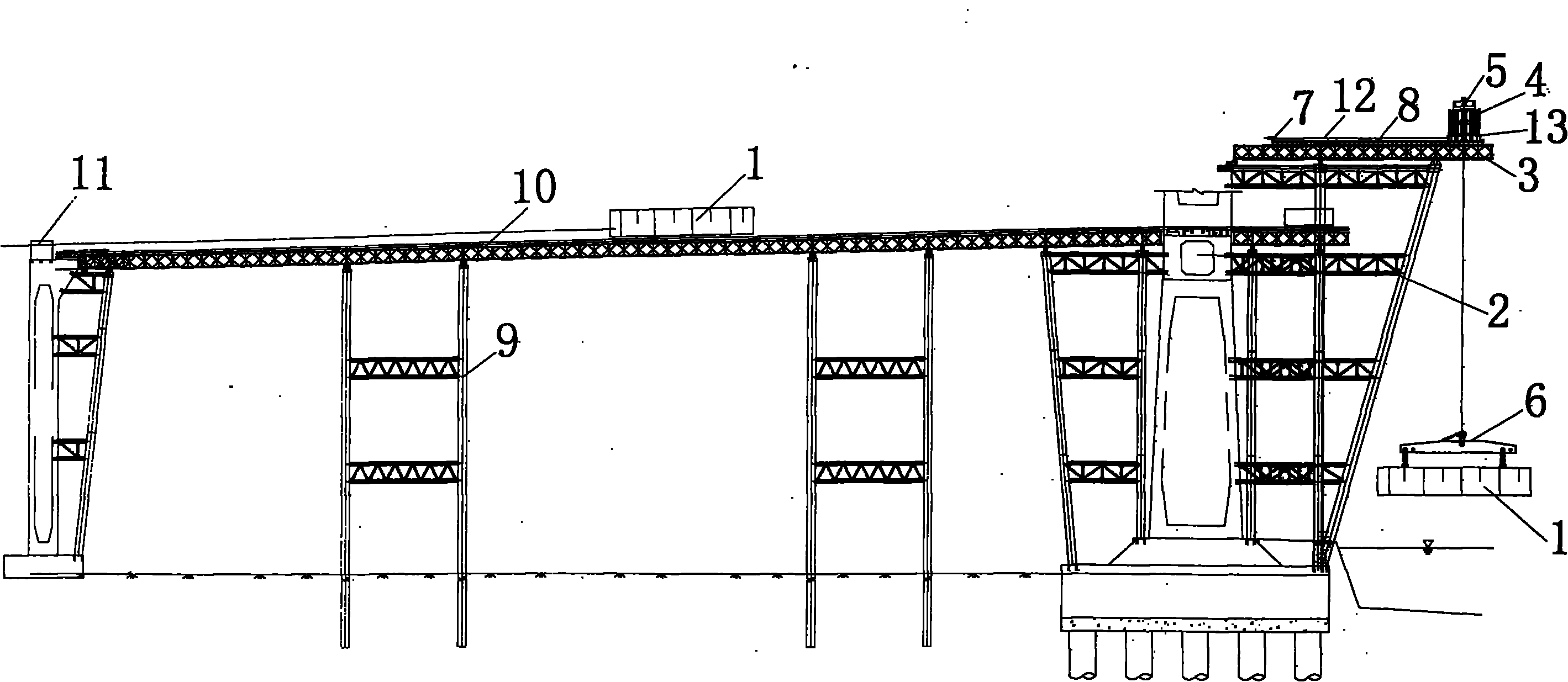
[0024] Such as figure 1 , figure 2 As shown, the present invention is a lifting system for large-tonnage steel box girder in land and shoal areas, which includes two parts: a hoisting system for steel box girder segments and a sliding platform;

[0025] The lifting system includes: lifting bracket 2, lifting longitudinal beam 3, lifting beam 4, lifting device 5 and walking device; the lifting system is arranged next to the pier near the channel, and the river bed at the position of the lifting bracket is excavated to Meet the needs of transportation and parking of steel box girder segments. The traveling device includes: traveling base 13, slide 8, jack 7, steel strand 12, PTFE sliding pl...


PUM


Abstract

The invention relates to the technical field of bridge construction, and discloses a system for lifting and sliding a large-tonnage steel box girder in a land area and a shoal area and a construction method thereof. The method comprises the following steps of: 1, arranging a lifting system beside a pier adjacent to a waterway, and arranging a sliding system below the lifting system and on a land side; 2, conveying a steel box girder section to a lifting position from the waterway, and lifting the steel box girder section by using a lifting device; 3, drawing a lifting transverse beam by using a jack and a steel stranded wire which are arranged on a lifting longitudinal beam to ensure that the lifting transverse beam, together with the lifting device and the steel box girder section, slides to a position above a sliding platform along the lifting longitudinal beam; 4, descending the steel box girder section to the sliding platform by using the lifting device; and 5, sliding the steel box girder section to a design position along a sliding track by using drawing equipment and arranging in position. The problem that a large floating crane is limited by the water level of a river channel and influenced by tide is solved, the construction period of a single steel box girder section is shortened, and work efficiency is improved; meanwhile, the steel box girder section can be arranged in the shoal area and the land area.

Description

Technical field [0001] The invention relates to the technical field of bridge construction, in particular to a lifting and sliding system for large-tonnage steel box girder in land and shoal areas and a construction method thereof. It is suitable for when large-tonnage steel box girder is prefabricated by the factory and transported to the bridge site by waterway. The large lifting station installed at the bridge site is used to lift and move longitudinally to the design position and install it in place to realize the steel box girder. The whole segment is hoisted in place. Background technique [0002] In the existing bridge construction, the large-tonnage steel box girder is usually manufactured by factory processing, and is transported to the construction site by waterway, and the large floating crane is used for lifting and installation. This method usually requires high navigable water level at the construction bridge site. Moreover, it takes a long time to occupy the chann...

Claims


Application Information

Patent Timeline
Patent Type & Authority Applications(China)
IPC IPC(8): E01D21/06
Inventor 王晓敬黄中华秦顺全张金杯夏邦军许佳平陈亚强魏焕堂钱云龙张建红
Owner THE 2ND ENG CO LTD MBEC
Why Eureka
Try Eureka