Connecting structure and installation method for piston and piston rod

A technology of connection structure and installation method, applied in the direction of piston rod, piston, piston ring, etc., can solve the problems of high processing technology requirements, piston shifting, easy desoldering, etc., to solve the problem of easy deformation and desoldering, and enhance locking The effect of fixing force and reducing production cost

Inactive Publication Date: 2011-07-20
CHENGDU SANHUAN METAL PROD
View PDF6 Cites 9 Cited by
  • Summary
  • Abstract
  • Description
  • Claims
  • Application Information

AI Technical Summary

Problems solved by technology

This method is cumbersome to process, with many procedures and high processing technology requirements, and after heat treatment and finishing, the welding and sealing fixed parts are relatively weak and easy to desolder, brittle cracks, resulting in oil leakage in the cracks and even piston displacement.
[0005] The third method is to find a thick material and directly process it into the integral parts of the piston and the piston rod. This method is troublesome to process, has many procedures, requires high processing technology, and is expensive.

Method used


Image

  • Connecting structure and installation method for piston and piston rod
  • Connecting structure and installation method for piston and piston rod
  • Connecting structure and installation method for piston and piston rod

Examples


Embodiment 1

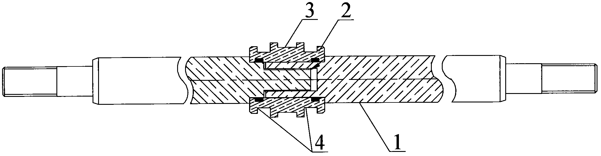
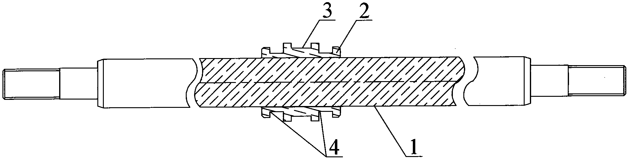
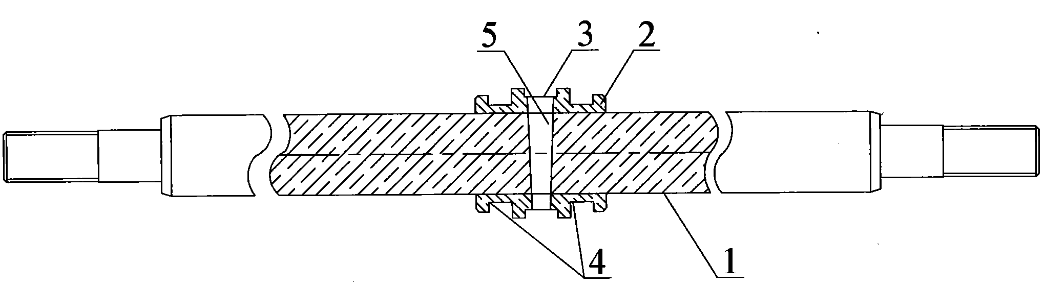
[0043] Such as image 3 As shown, the connection structure between the piston rod 1 and the piston 2 is: the piston 2 is directly sleeved on the piston rod 1, and the piston 2 and the piston rod 1 are in an interference connection, and there is no seal between the piston 2 and the piston rod 1 Under the premise of the ring, it can also achieve a tight sealing and locking state. The outer wall of the piston 2 is also provided with a wear-resistant pad slot 3 and a sealing ring slot 4. The number of the wear-resistant pad slot 3 and the sealing ring slot 4 is more than one, and the wear-resistant pad slot 3 is installed Wear-resistant pad, because the overall structure of piston 2 and piston rod 1 is sliding in the oil rod, the outer side of piston 2 will rub against the inner wall of the oil rod, thereby causing wear to the outer wall of piston 2 and the oil rod, after installing the wear-resistant pad Will reduce the wearing and tearing to piston 2 and oil rod, and get final ...

Embodiment 2

[0052]The only difference from Example 1 is that the piston 2 is also provided with a tapered pin hole 5 passing through the piston rod 1 from one side to the other side, and the tapered pin hole 5 is located on the wear-resistant pad in slot 3. Since the wear-resistant pad groove 3 is located in the middle of the piston 2 , the taper pin hole 5 is also located in the middle of the piston 2 . The main function of the taper pin hole 5 is to install the taper pin, thereby enhancing the locking force of the piston. Whether the taper pin hole 5 is set or not is determined according to the actual situation, and the number of settings is also determined according to the actual situation. In this embodiment, the number of the taper pin hole 5 is more than one, and it is set around the central axis of the piston rod 1, and the central axis It may not intersect with the central axis of the piston rod 1, but in order to enhance the locking effect, in general, the central axes of the ta...

Embodiment 3

[0055] The difference with Embodiment 2 is only that: when the width of the wear-resistant pad slot 3 is small, all the tapered pin holes 5 can only be arranged on the same circumference, that is, the central axes of all the tapered pin holes 5 must be in the same plane. A problem that exists at this moment is exactly: if all taper pin holes 5 are processed at one time, because the central axes of all taper pin holes 5 all intersect and have only one intersection point, this intersection point is exactly each taper pin hole 5 central axes and the piston. The intersection point of the central axis of the rod 1 is defined as the center point. After installing a taper pin, this center point is occupied, so that other taper pins cannot be installed.

[0056] The structure of the above-mentioned taper pin 5 requires its processing steps as follows: (a) drill a taper pin hole 5 in the wear-resistant pad groove (3) of the piston 2, and its axis is in a plane perpendicular to the cent...


PUM


Abstract

The invention discloses a connecting structure for a piston and a piston rod. The connecting structure mainly comprises the piston rod and the piston sleeved on the piston rod, wherein the piston is in interference fit with the piston rod; the outer wall of the piston is provided with a wear-resistant pad clamping groove and a sealing ring clamping groove; and the piston is provided with a tapered pin hole which passes through the piston rod from one side to the other side and is positioned in the wear-resistant pad clamping groove. The piston is in interference fit with the piston rod according to an expansion and contraction principle of metal, so that the piston and the piston rod are tightly sealed and locked; the tapered pin hole is drilled in the middle of the piston, so that the locking fixing force of the piston is increased, and the piston does not move or drain oil on the piston rod during work; and production benefit is improved, and production cost is reduced.

Description

technical field [0001] The invention relates to the field of installation of a piston and a piston rod, in particular to a connection structure of a piston and a piston rod and an installation method thereof. Background technique [0002] The assembly and manufacture of the piston and piston rod of the existing hydraulic PE hot-melt butt welding machine can be roughly divided into three methods. Among them, the materials used for the piston parts do not need any heat treatment and can be made of non-ferrous metal materials. The piston rod parts require quenching and tempering heat treatment. , the outer surface needs electroplating treatment. The three processing methods are as follows: [0003] The first method is as figure 1 As shown, the piston rod is divided into two sections, which are put on both ends of the piston and then locked by thread. Since the thread lock needs to be rotated, the piston and the piston rod are slidingly connected, and must be assembled between...

Claims


Application Information

Patent Timeline
Patent Type & Authority Applications(China)
IPC IPC(8): F16J1/12F16J1/01F16J7/00F16J9/00
Inventor 王智勇
Owner CHENGDU SANHUAN METAL PROD
Why Eureka
Try Eureka