
Automatic compensation device and method for background field of fluxgate magnetometer

An automatic compensation and magnetometer technology, applied in the direction of the size/direction of the magnetic field, magnetic field measurement using the principle of magnetic flux control, etc., can solve the problems of low compensation efficiency, inconvenient operation, and inability to implement automatic operation, so as to improve compensation efficiency and The effect of precision

Inactive Publication Date: 2011-07-20
INST OF GEOPHYSICS CHINA EARTHQUAKE ADMINISTRATION
View PDF2 Cites 9 Cited by
  • Summary
  • Abstract
  • Description
  • Claims
  • Application Information

AI Technical Summary

Problems solved by technology

These compensation methods require on-the-spot operation and are not suitable for remote control, such as the compensation of downhole magnetometers or networked remote monitoring; and the operation is inconvenient and the accuracy is low; some operations are cumbersome, requiring repeated measurements and settings, and the compensation efficiency is low
Although some fluxgates use the method of digitally setting the compensation value, they need to measure the background magnetic field in advance, cannot implement automatic operation, and the compensation accuracy is also low

Method used


Image

  • Automatic compensation device and method for background field of fluxgate magnetometer
  • Automatic compensation device and method for background field of fluxgate magnetometer
  • Automatic compensation device and method for background field of fluxgate magnetometer

Examples


Embodiment Construction

[0052] The principles and features of the present invention are described below in conjunction with the accompanying drawings, and the examples given are only used to explain the present invention, and are not intended to limit the scope of the present invention.

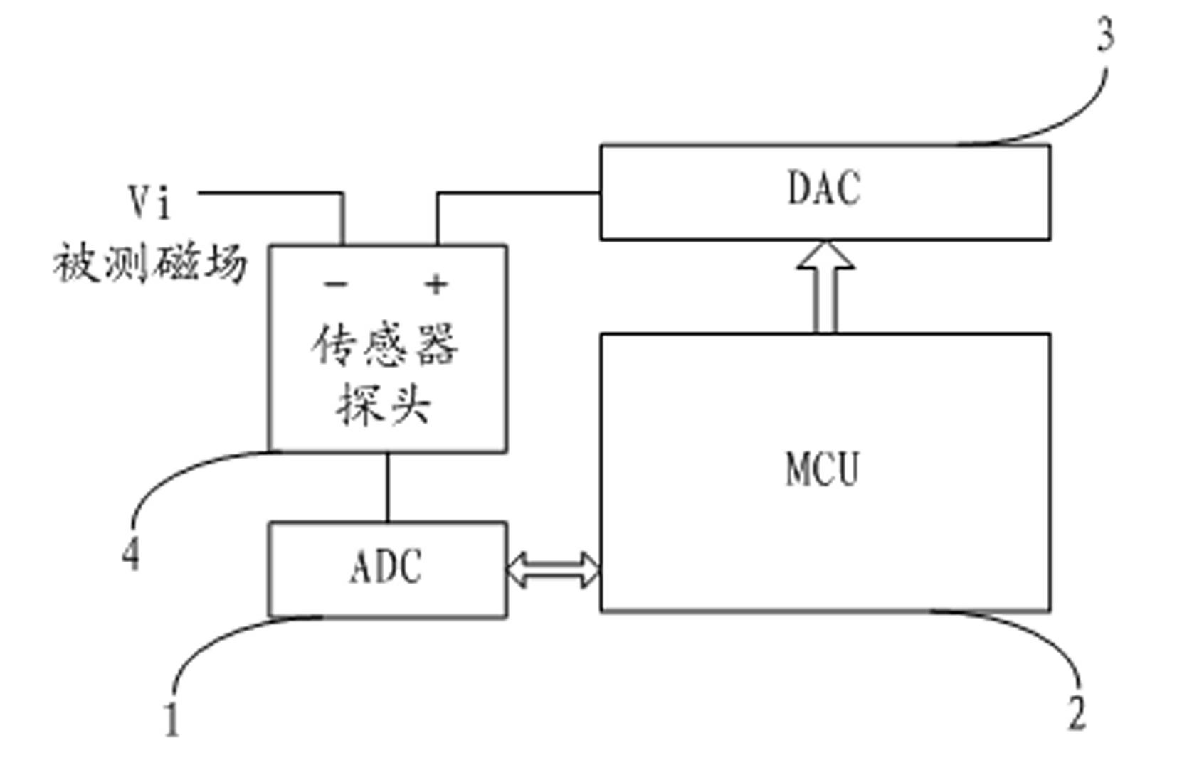
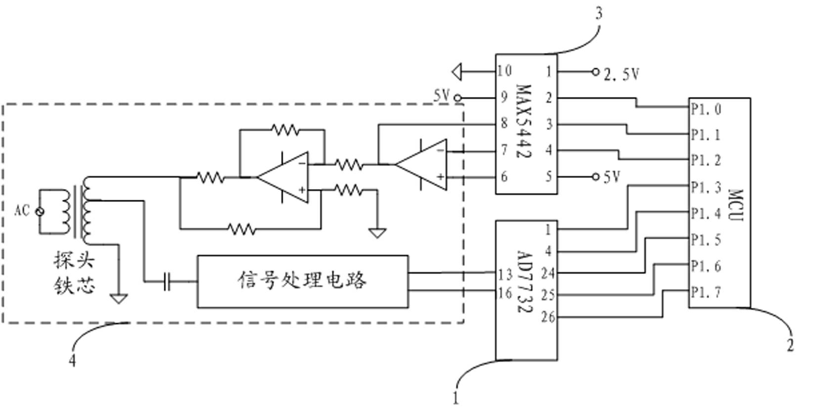
[0053] Such as figure 2 As shown, the fluxgate magnetometer background field automatic compensation device of the present invention comprises the A / D converter 1 electrically connected with the sensor probe 4 of the fluxgate magnetometer, the MCU 2 electrically connected with the A / D converter 1, And the D / A converter 3 that is electrically connected with the MCU 2 and is electrically connected with the compensation coil in the sensor probe 4 of the fluxgate magnetometer; wherein, the A / D converter 1 is used for real-time acquisition of the fluxgate magnetometer measurement value And convert it into a digital signal for MCU 2 operation processing, MCU 2 is used to control the A / D converter 1, and perform operation ...


PUM


Abstract

The invention relates to an automatic compensation device and method for a background field of a fluxgate magnetometer. The device comprises an analog / digital (A / D) converter, a micro control unit (MCU) and a D / A converter; the A / D converter acquires the measurement value of the fluxgate magnetometer from a sensor probe of the fluxgate magnetometer, converts the measurement value into a digital signal in real time and provides the digital signal for the MCU for operation; and a digital compensation signal obtained by operation of the MCU is converted into an analog voltage signal through the D / A converter, and the analog voltage signal is coupled to a compensation coil in the sensor probe of the fluxgate magnetometer. The method comprises the following steps of: acquiring signals by the A / D converter; judging whether compensation is needed and giving the magnitude and the direction of an initial compensation value by the MCU, and outputting compensation current by the D / A converter; repeating the compensation cycle; and placing the sensor probe in a quasi-zero field by a plurality of compensation cycles. In the invention, manpower for operating instruments on site is not needed, compensation efficiency and precision are improved, and the device and the method can be used for deep well observation and remote monitoring and intelligent measurement of the instruments.

Description

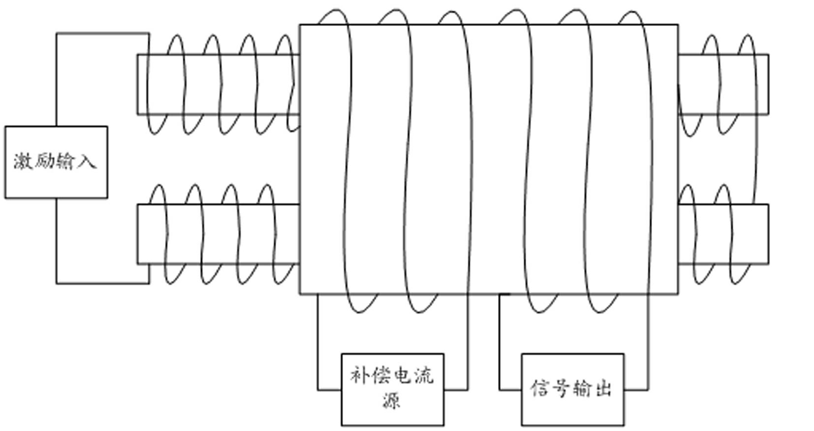
technical field [0001] The invention relates to a background field automatic compensation device and a background field automatic compensation method applied to a fluxgate magnetometer. Background technique [0002] A fluxgate magnetometer is an instrument suitable for measuring magnetic fields under zero and weak magnetic fields. When it is used to measure the weakly changing magnetic field under the strong magnetic field background, such as observing the change of the geomagnetic field, that is, the "relative observation" of the geomagnetic field, it is necessary to compensate the main magnetic field (background field or basic geomagnetic field) to make the magnetometer probe iron The core works near zero field, so that its resolution, dynamic range and linear characteristics can meet the requirements of recording changes in geomagnetic field components. The compensation method is to add a compensation coil to the probe core, pass the compensation current, and generate a ...

Claims


Application Information

Patent Timeline
IPC IPC(8): G01R33/04
Inventor 滕云田胡星星张炼马洁美张旸
Owner INST OF GEOPHYSICS CHINA EARTHQUAKE ADMINISTRATION
Learn More